Surfaces > Rolled Edge > Panel Gap
Creates the many surfaces that define a finished gap, along a set of tangent continuous surface curves, including the flanges (that define the edges) , the fillets between the panel and the edges, and an optional close-out surface at the bottom of the gap.
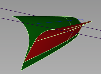
Anatomy of a Panel Gap
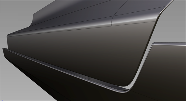
Example of a panel gap.
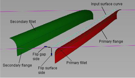
To build a gap within a panel surface, you need, at a minimum, one or more tangent continuous (G1) surfaces curves on the panel. Optionally, you can also build the gap between a set of G1 surface curves, and a separate set of surfaces.
As with the Fillet Flange tool, an imaginary "wall" surface is first built off the surface curves, to help define the primary fillet. (The wall is not actually added to the model.)
Instead of having explicit wall options like the Fillet Flange tool, Panel Gap uses the Primary Flange options to define the wall.
If the primary flange Type is set to Parting line, the wall uses the Primary Vector direction plus the Draft angle as the draft direction. If the primary flange Type is set to Sweep angle, the wall is based on the direction of the surface normal at the selected curve.
The primary fillet and flange are created in the same way as with the Fillet Flange tool.
The primary and secondary fillets can be either tangent (G1) or curvature (G2) continuous with the panel surface. The same control options found in other rolled edge tools are available: a Form factor slider, and the ability to specify either the Center radius, Tangent offset, or Both for each fillet.
By default, both Primary Section Type and Secondary Section Type are set to G1 Tangent.
The primary fillet is built between the panel surface and the (imaginary) wall. The location of the secondary fillet is calculated from the radius of the primary fillet, gap distance, and radius of the secondary fillet.
Panel Gap Control
Fillets-Flanges
Flip surface side
Check or uncheck this box to reverse the direction of the fillets and flanges. This has the same effect as clicking the blue arrow that appears normal to the panel surface.
Flip gap side
Check or uncheck this box to switch the direction of the fillet in order to position the gap on the other side of the surface curve. There is a corresponding blue arrow on the model that you can click to switch the direction as well.
Gap Position
Specifies where the gap is located with respect to the input curves, as shown below.
Center line – Centers the gap over the input curves.
Primary side – Builds the primary geometry at the location of the input curves and positions the gap on one side or the other.
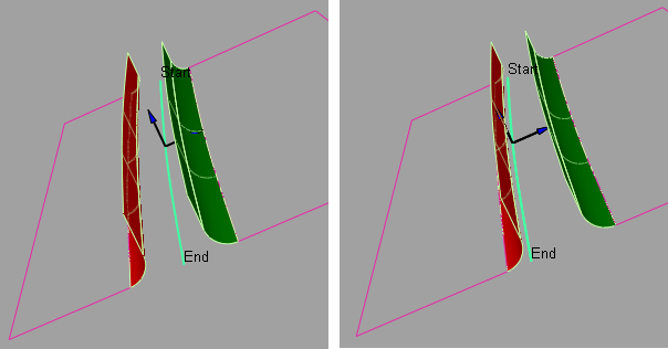
Left: Center line. Right: Primary side
Variable geometry
When this box is checked on, you can click on the input surface curve(s) to position manipulators that allow you to vary the gap distance (default), the direction of the primary vector, or the direction of the secondary vector (see Create Manip below) along the length of the gap.
Create Manip
Specifies the type of manipulator that is created when you click the input curve.
Gap – The gap manipulators control the width of the gap. They appear as straight lines across the gap.
Primary Vector – The primary vector manipulators control both the draft direction and the primary flange direction. These manipulators appear as purple arrows.
Secondary Vector – The secondary vector manipulators control the secondary flange direction. These manipulators appear as yellow arrows.
See the section Using the manipulators to create a variable gap.
Gap distance
Specifies the initial width of the panel gap. The gap corresponds to the shortest distance between the primary and secondary rolled edges.
Closeout Flanges
Check on this box to create a ruled surface joining the bottom edges of the primary and secondary flanges (when both are present).
Primary Section Type
Choose either G1 Tangent or G2 Curvature for the continuity of the primary fillet with the panel surface.
Secondary Section Type
Choose either G1 Tangent or G2 Curvature for the continuity of the secondary fillet with the panel surface.
Explicit control
Gives you control of the surface degree and maximum number of spans in the fillet and flange surfaces.
The following options appear for each fillet. See also Surfaces > Rolled Edge > Fillet Flange for more information on these options.
Specify
Choose whether you want to specify the Center radius, Tangent offset, or Both.
If Specify is set to Center radius or Tangent offset, and you also set the Form factor, the third parameter (either Tangent offset or Center radius) varies along the fillet. Both lets you specify both the Tangent offset and Center radius of the fillet, but not the Form factor. The form factor is calculated automatically from these two values and varies along the fillet.
Center radius
Radius at the center of the fillet (as measured along the arc length).
Tangent offset
Radius of a sphere that is tangent to the input surface(s) at the contact line, and is also tangent to the wall. (The contact line is the line along which the new fillet surface touches the input surfaces.)
Form factor
This parameter lets you adjust the shape of the fillet. It specifies the ratio between the lengths of the innermost and outermost CV arms of the hull in the V direction of the fillet. Values range from 0.1 to 2.0. The smaller the value, the sharper the bend in the fillet.
Explicit Control Options
This section appears when Explicit Control is checked on.
U degree
The degree of the fillet and flange surfaces in the U direction (that is, along the edge). Enter a whole number from 3 to 6. This option is only available when Explicit Control is checked.
V degree
The degree of the fillet surfaces in the V direction. Enter a whole number from 3 to 6. This option is only available when Explicit Control is checked.
The degree of the flange surfaces in the V direction is always 1, since they are ruled surfaces.
Maximum spans
If Surface Type is set to Multiple surfaces, this value specifies the maximum number of spans for each fillet and flange surface. If Surface Type is set to Single surface, it specifies the maximum number of spans for each piece of the original surfaces.
This option is only available when Bezier Surfaces is not checked.
Primary Flange / Secondary Flange
The options to control the primary and secondary flange are the same, with the addition of a third Type called Relative to Primary for the secondary flange.
Type
Sweep angle – The flange us defined by a Sweep angle, which is the angle between the flange and the input surface.
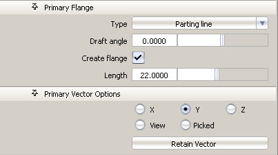
Parting line – The flange is defined by the direction of a vector (specified through the Primary/Secondary Vector Options) plus a Draft angle.
Relative to Primary – This option only applies to the Secondary Flange. It lets you change the Draft angle or Sweep angle of the secondary flange relative to the first flange. This is useful to create a gap with zero width and coincident flanges, as shown below.
Sweep/Draft angle
Provides a slider to control the angle of the flange. The default is 90 degrees for Sweep angle, and 0 degrees for Draft angle.
Create flange
Determines whether or not a flange will be built off the edge of the fillet.
Length
Specifies the length of the flange, if Create flange is checked on
Primary Vector Options / Secondary Vector Options
These options only apply when Type for the corresponding flange is set to Parting line.
X, Y, Z – Select one of these to specify a pull direction along that axis.
View – Select this option to specify a pull direction normal to the current view. The vector is not drawn in the view windows.
Picked – Selecting this option lets you specify the name of an existing vector in the Picked Vector field, or pick the vector in the view. This vector defines the pull direction.
Refresh View Vector – This button only appears if View is selected. Click it to update the vector if the view has been modified.
Retain Vector – Click this button to create a vector construction object in the view windows. Unless you do this, the vector direction you specified is used by the tool, but you will not see and be able to re-use the vector.
Fillet-Flange Range
Modify primary range / Modify secondary range
Checking on these boxes causes arrow manipulators to appear on the fillets. Drag these arrows to modify the extent of the fillets and flanges across the main panel. You can drag the arrows all the way to the edges of the input surfaces. The arrows also snap to curve intersections according to the options set in the Curve Snap Options window.
Primary and Secondary start / end sliders also appear in the control window and can be used instead of dragging the arrows. Setting the sliders to 0.0 and 1.0 resets the original extent.
When the boxes are unchecked (default), the fillets and flanges extend to the edges of the input surfaces.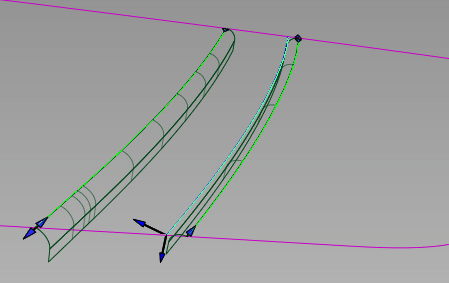
Evaluation
Gap check
Turn on this option to show a deviation comb, as well as minimum and maximum deviation at the gap location.
Additional options appear to let you control the deviation locator.
Closest point samples
The number of quills displayed on the deviation comb.
Comb scale
Increase this value to see small variations in the deviation comb.
Threshold
Acts as a tolerance, and is most useful in the case of a constant gap width. If the gap is within that value of the requested Gap distance, the deviation quill is green, otherwise it is red.
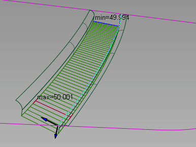
Here Gap distance = 50.0 and Threshold = 0.1
Surface Structure
These controls apply to both primary and secondary fillets and flanges simultaneously. They are the same as in Fillet Flange.
Surface type
Single surface – A single fillet and flange surfaces are built on each side of the gap.
Multiple surfaces – The fillets and flanges are split at the boundaries of the input curves and surfaces.
Curves-on-surface created at the edges of the fillets (visible when Auto Trim is off) are segmented to correspond to the multiple fillet/flange surfaces.
Bezier surfaces
This option only appears if Surface Type is set to Multiple surfaces. If it is checked on, each surface will be a Bézier patch.
Bézier patches have a single span, and their maximum degree in the U direction is set through the Explicit Control section. The default is degree 5.
Short Edge Tolerance
In the case of cross-knot insertion, the system will not allow spans of a length smaller than the Short Edge Tolerance.
Control Options
Trim Type
Off – Does not trim the panel surfaces.
Curves-on-surface – Places curves-on-surface on the panel surfaces at the fillets edges, without trimming.
Automatic – Automatically trims the panel surfaces to the edges of the fillets, provided the fillets extend to the ends of the surfaces. You may need to use the Fillet-Flange Range options to extend the fillets. This is the default.
Auto Update
Automatically updates the fillet and flange surface(s) as you change the options.
If your geometry is very complex and takes a long time to update, turn this option off and click the Update button when you want to update the surfaces.
Continuity Check
Choose whether to get visual feedback about primary and secondary fillet continuity with the panel surface(s). Green indicates success; yellow indicates that the continuity condition has not been met.
Chain Select
If this box is checked, selecting a surface curve also selects all other surface curves that are tangent continuous with it.
Create Metadata
Specifies whether or not the Panel Gap tool creates history metadata.
The Create Metadata option is available only with Autodesk Alias 2019.2 or later.
Buttons
Reset
Restores your saved settings. If you have not saved custom options, Reset restores the installed option settings.
Update
Updates the surfaces with the current settings when Auto Update is off.
Undo All
Reverses any effects of the tool.
Next
Resets the tool to begin a new panel gap.
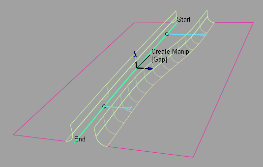
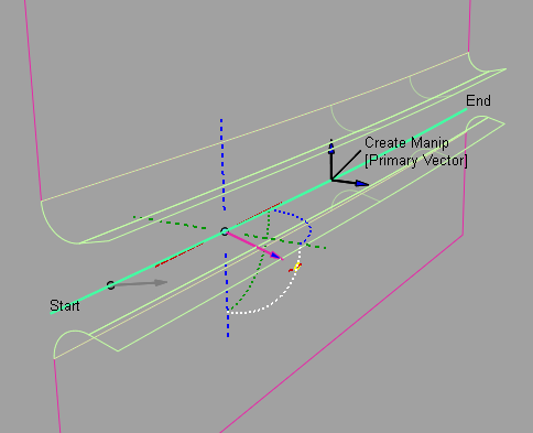
Using the manipulators to create a variable gap
When Variable geometry is checked on, you can control the width of the gap, or the direction of the primary and secondary flanges by placing and adjusting manipulators along the gap.
A label called Create Manip [Gap] appears on the model near the center of the input curve. Clicking on [Gap] toggles between [Primary Vector], [Secondary Vector], then back to [Gap]. This determines the type of manipulator that will be created when clicking the input curve. The behavior is the same as setting the Create Manip option in the control window.
Each manipulator consists of two handles, one at each end. Click on a handle to change its value (it turns white) or simply roll over it to see the value (it turns yellow). Hold  and click on a manipulator to remove it.
Only manipulators of the type indicated by the Create Manip label can be modified. Others are drawn in grey. The prompt line gives feedback while using the manipulator controls.
Gap manipulator
Click and drag the small circle to slide the manipulator along the curve, or type a parameter value on the keyboard and press
 .
.Click and drag the small triangle to change the gap distance at that location, or type a value on the keyboard and press
.
The gap widths between the edge of the panel and the first manipulator, as well as between the opposite edge of the panel and the last manipulator, are constant. The width between any pair of interior manipulator is interpolated.
Vector manipulators
Clicking a primary or secondary vector displays full manipulator controls, including arcs for X, Y, and Z rotations, axes for alignment along X, Y or Z, and a small circle for unconstrained motion in all directions.
The primary and secondary vectors can be aligned to existing vector objects. Click on the arrow of a Primary Vector or Secondary Vector manipulator, then click an existing vector object to set the draft direction at the given location to that of the vector, or type three values (X, Y, Z) on the keyboard and press
.For both Primary Vector and Secondary Vector manipulators, the vector direction between the edges of the panel and the nearest manipulator remains constant. Between any pair of interior manipulators, the vector direction is interpolated.