Surfaces > Multi-Surface Blend > Freeform Blend
Previously called Freeform fillet, Freeform Blend enables you to create a transitional surface based on two input contact lines. Those contact lines can be surface curves or free curves.
If a contact line is made up entirely of free curves, that side reverts to G0 Position continuity. As well, Edge align is not possible on that side. If a contact line is made up of both free curves and surface curves, then up to G1 Tangent continuity is allowed on that side. Edge align can be attempted only for the surface curve sections.
Freeform Blend Control
Side 1 Continuity/Side 2 Continuity
Choose G0 Position, G1 Tangent, G2 curvature or G3 curvature to determine the type of continuity that will be used between the blend surfaces and primary surfaces. The continuity settings can be specified independently along both sets of boundaries.
G2 curvature continuity means that the curvature (which is the inverse of the radius of curvature) is the same on both sides across the blend surfaces’s boundaries.The V degree of the blend surface is adjusted so that the surface has enough CVs to provide the required continuity on both sides. Degree 4 is needed for G2 continuity on one side, and degree 5 is needed for G2 continuity on both sides
G3 curvature continuity means that the curvature’s rate of change is the same on both sides across the blend surfaces’s boundaries. The V degree of the blend surface is adjusted so that the surface has enough CVs to provide the required continuity on both sides. Degree 6 is needed for G3 continuity on one side, and degree 7 is needed for G3 continuity on both sides.
Blend Control
Choose the method for controlling the shape of the blend.
Form Factor – Use the Form Factor value to control the shape.
Shape – Use the Shape values to control the shape.
Form Factor
This parameter lets you adjust the shape of the blend. It specifies the ratio between the lengths of the innermost and outermost CV arms of the hull in the V direction of the blend. Values range from 0.1 to 2.0. The smaller the value, the sharper the bend in the blend.
This option is only available when both Side 1 and Side 2 Continuity are the same (G1 Tangent, G2 Curvature, or G3 Curvature only).
Lock Shape Controls
When this option is checked on, the values of Side 1 Shape and Side 2 Shape are kept the same.
Side 1 Shape
Provides control over the “looseness” or “tightness” of the blend surface toward the first boundary. If the value is greater than 1.0, the result is a blend that fits tighter to the corner of the input surfaces; if the value is less than 1.0, the result is a rounder blend that fits closer to the edge of the first surface.
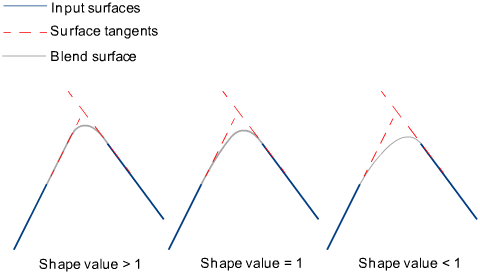
Side 2 Shape
Provides control over the “looseness” or “tightness” of the blend surface toward the second boundary. If the value is greater than 1.0, the result is a blend that fits tighter to the corner of the input surfaces; if the value is less than 1.0, the result is a rounder blend that fits closer to the edge of the second surface.
Modify Parameter
When on, you can use the Side 1 Parameter and Side 2 Parameter options to adjust the location of the contact line between the freeform blend and the side 1 or side 2 surface.
Use the in-canvas manipulator or the control sliders to set the Side 1 Parameter and Side 2 Parameter values.
Crown Mode
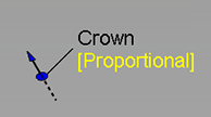
When Side 1 Continuity and Side 2 Continuity are both set to G0 Position, this option lets you raise or lower midpoint or top of flat blends using a crown. Choose between adding a Proportional Crown or an Absolute Crown. You can also switch between the crown modes using the in-canvas manipulator. Click below the Crown label and choose between Proportional Crown, Absolute Crown, or Off.
Proportional Crown
Select this option to create a crown with a height that is proportional to the distance between the original curve and the top of the blend surface.
Absolute Crown
Select this option to create a crown that has a consistent height across the blend section regardless of the width or distance between the curves. Use the Absolute Crown Value to set crown height to an absolute value based on the set scene units.
Crown Mode is set to off when you load a WIRE file that includes history results for Absolute Crown into versions previous to Alias 2022.2 Update.
Crown Value
Controls the height of the crown. Proportional Crown Value - The value corresponds to a percentage of the distance between the two rails. The slider ranges from 0.0 to 0.1, but larger values can be entered into the field.
Absolute Crown Value - Sets the crown height to an absolute value based on the set measurement units. The slider ranges from 1 to 10, but larger values can be entered into the field.
To change the Crown Value using the in-canvas manipulate, drag the arrow. The value adjusts in 0.005 increments. Use the left mouse button for adjustments, the middle mouse button for fine adjustments.
Flip
Flips the direction of the crown.
Click the arrow on the crown manipulator to flip the crown direction directly on the model.
Crown Value
Controls the height of the crown. The value corresponds to a percentage of the distance between the two rails. The slider ranges from 0.0 to 0.1, but larger values can be entered into the field.
Crown Shape
Increase the degree of the surface from 2 to 3, giving two central rows of CVs. Shape values less than 1 move these CVs closer to the edges of the surface, positive values move them closer to the center.
Crown Position
Controls the U direction of the crown shape between the middle of the blended surface toward either input surface. When set to 0, the crown shape is at the middle of the blend surface. Increasing or decreasing this value moves the crown shape towards either input surface. Crown Shape must be set to a value greater than 0 before Crown Position has any effect.
Explicit Control
Gives you controls of the surface degree and maximum number of spans in the new blend surface.
Explicit Control Options
These options are only available when Explicit Control is checked.
U Degree
The degree of the new blend surface. Enter a whole number from 2 to 9.
Max. Spans
If Surface Type is set to Multiple surfaces, this value specifies the maximum number of spans for each blend surface. If Surface Type is set to Single surface, it specifies the maximum number of spans inside each pair of boundaries between the original surfaces.
This option is only available when Explicit Control is checked, and Bézier Surfaces is not checked.
Flow Control
Start/Interior/End
Controls how the blend surface(s) edges (in the V direction) meet up with the edges of the boundary surfaces.
Edge align – The tool tries to colinearly align the blend surfaces’ edges or isoparms (for single surface) to the edges of the boundary surfaces in the V direction.
Connect ends – The edges of the blend surfaces meet the start and/or end points of the boundaries exactly.
Default or Free – The edges of the blend surface(s) (in the V direction) meet the boundaries at a 90 degree angle.
Clicking the labels on the model lets you cycle through all the possible values.
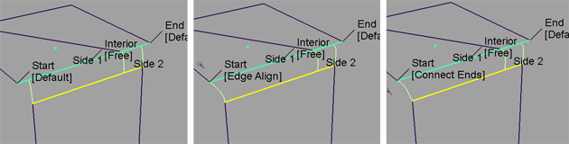
Possible flow control values for Start of blend
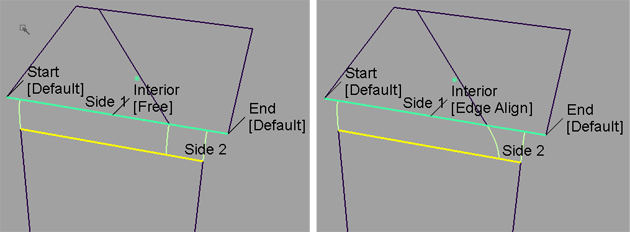
Possible flow control values for Interior of blend
Modify Range
When this option is selected, Primary/Secondary Start and End sliders appear in the control window. Unless the Flow Control for the Start and/or End is set to Edge align, these sliders are available, and arrow manipulators appear on the blend surface(s). Drag these arrows to modify the extent of the blend surface(s) across the input surfaces.
Primary start / Primary end / Secondary start / Secondary end
Use these sliders to modify the extent of the tangent lines that are used to build the blend. Start and End values of 0.0 and 1.0 respectively, define the original extent.
These are not available if the Flow Control is set to Edge align for either the Start or End.
Surface Structure
Surface Type
If you choose Single surface, a single blend surface is built. If you choose Multiple surfaces, multiple surfaces, corresponding to the boundaries between the original surfaces, are created. (Extra spans are added, if necessary, to meet tangent or curvature requirements.) This gives you much lighter blend surfaces and better continuity with the original surfaces.
The output of a single surface blend (Surface Type set to Single surface) is a degree-2 surface. For multiple surface blends (Surface Type set to Multiple surface) the degree type is inherited from the input surfaces, which can typically be degree-3.
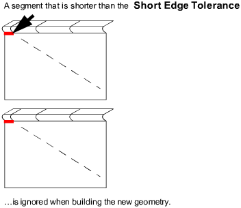
Short Edge Tolerance
In the case of cross-knot insertion, the system will not allow spans of a linear distance less than the Short Edge Tolerance.
Bézier Surfaces
This option only appears if Surface Type is set to Multiple surfaces. If it is checked on, each surface will be a Bézier patch.
Bézier patches have a single span, and their maximum degree in the U direction is set through the Explicit Control section. The default is degree 5.
Control Options
Trim Type
Off – Does not trim the original surfaces.
Curves-on-surface – Creates curves-on-surface along the contact lines, allowing you to trim manually.
Automatic – Automatically trims the original surfaces back to the contact lines.
Auto Update
Automatically updates the blend surface as you change options. If the surface to be built is very complex and takes a long time to update, turn this option off and click the Update button when you want to update the surface.
Inter Continuity Check
Checking on this option displays continuity locators between the output surfaces, indicating whether or not they are tangent continuous. Green T locators indicate that the surfaces are tangent continuous while red/yellow T locators indicate they are not.
The Continuity Angle fromPreferences > Construction Options is used when testing for tangent continuity, and a shared boundary is only checked if it doesn't present any gap larger than the Topology Distance tolerance (also found in Construction Options).
Only natural (non-trimmed) edges are checked.
Continuity Check
Displays a manipulator indicating continuity achieved with the existing surfaces along the blend surface edges.
Chain Select
If this box is checked, selecting a boundary input curve also selects all other boundary curves that are tangent continuous with it.
Create Metadata
Specifies whether or not the Freeform Blend tool creates history metadata.
The Create Metadata option is available only with Autodesk Alias 2019.2 or later.