Surfaces > Multi-Surface Draft
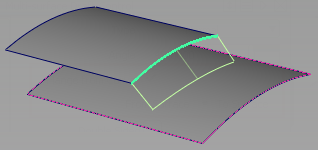
Creates one or more ruled surfaces by pulling a group of surface curves at an angle to the normal of the original surface(s), or by pulling any number of curves at an angle to a pull vector. The curves can be continuous or disjoint.
The Multi-Surface Draft tool uses surface edges, curves on surface, isoparametric curves, and in Draft mode, even free curves, to create a ruled surface (or group of surfaces) that extends away at an angle to the original surface (or curve).
A ruled surface is flat at every point in a given direction.
You can build a single surface across all of the input curves, provided that they are tangent continuous.
Other related tools are Surfaces > Rolled Edge > Fillet Flange  .
.
Multi-Surface Draft Control options
Type
Normal – Creates a surface that extends away at a given angle from the normal of the underlying surface(s). By default, the new surface is normal to the underlying surface(s).
Draft – Creates a surface that extends away at a given angle from a specified pull direction vector. By default, the surface is parallel to the pull vector.
In this mode, you can individually select, or box-select, any combination of curves (even free curves), whether they are disjoint (non-touching), G0 (position continuous) or G1 (tangent continuous).
Use Construction > Vector  to create a vector object.!
Angle/Draft Angle
The initial angle between the new surface and the normal of the original surface (Normal type), or pull vector (Draft type). The default is 0.0. You can also change this value using the angle/length manipulator when you use the tool. (See Variable option below).
Length
The initial length of the surface from the original curves. You can also change this value using the angle/length manipulator when you use the tool. (See Variable option below).
Angle Calculation
The 3D Rotation calculation is based on Injection Molding. 2D Rotation produces better results with large draft angles.
Length Mode
Defines which distance the flange Length represents.
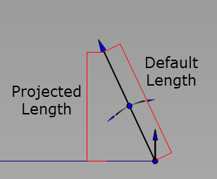
Default – The length of the flange is the length of the flange edge.
Projected – The length of the flange is the projected distance to the surface.
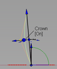
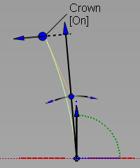
Crown Mode
Select this option to raise or lower the midpoint (top) of the draft surface using a crown. Choose between adding a Proportional Crown or an Absolute Crown. You can also switch between the crown modes using the in-canvas manipulator. Click below the Crown label and choose between Proportional Crown, Absolute Crown, or Off.
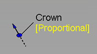
Proportional Crown
Select this option to create a crown with a height that is proportional to the distance between the original curve and the top of the draft surface.
Absolute Crown
Select this option to create a crown that has a consistent height across the section regardless of the section width or distance between the curves.
Crown Mode is set to off when you load a WIRE file that includes history results for Absolute Crown into versions previous to Alias 2022.2 Update.
Crown Value
Controls the height of the crown.
Proportional Crown Value - The value corresponds to a percentage of the distance between the two rails. The slider ranges from 0.0 to 0.1, but larger values can be entered into the field.
Absolute Crown Value - Sets the crown height to an absolute value based on the set measurement units. The slider ranges from 1 to 10, but larger values can be entered into the field.
To change the Crown Value using the in-canvas manipulate, drag the arrow. The value adjusts in 0.005 increments. Use the left mouse button for adjustments, the middle mouse button for fine adjustments.
Crown Shape
Increase the degree of the surface from 2 to 3, giving two central rows of CVs. Shape values less than 1 move these CVs closer to the edges of the surface, positive values move them closer to the center.
Flip Crown
Flips the direction of the crown. Click the arrow of the crown manipulator to Flip the crown direction directly on the model.
Crown Position
This option controls the U direction of the crown shape from the middle of the draft surface to either end. When set to 0, the crown shape is at the middle of the surface. Increasing or decreasing this value moves the crown shape towards either end of the draft surface. Crown Shape must be set to a value greater than 0 before Crown Position has any effect.
Crown Type
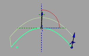
Central – The first and last CVs in the V direction follow the draft angle, and the surface crowns in the center of the draft surface.
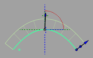
End – The first CV follows the draft angle, and the height of the crown is measured from the last CV relative to the draft angle.
To Surface
Creates a draft to a surface.
Radial
Orients the draft radially.
Radial off
Radial on
Refit
The Radial option creates a variation of the original draft surface. However, the radial surface does not follow the direction of the draft vector, so some radial draft surfaces may not meet the draft requirements. (The surface will fail the draft angle check in the Surface Evaluation diagnostic shader. The larger the angle between the default non-radial draft surface and the radial draft surface, the more likely the draft check will fail.)
To create a radial draft surface that satisfies the draft requirements, the Refit option attempts to refit the radial surface to the original draft surface, while still following the radial directions. It changes the radial draft surface to degree 2 in the draft surface length (V) direction, then aligns the upper row of CVs on the radial draft edge to the default non-radial draft surface, creating a crown. The resulting radial surface is closer to the original and produces better results when checking it with the Surface Evaluation diagnostic shader.
This method is successful in some cases, but not all.
Flange from Curve
Creates a flange from a curve.
To build a clean flange off a light weight curve that has been fit to a curve-on-surface, select Flange from Curve, From Surface.
To create a flange from a curve to a surface, select Flange from Curve, To Surface.
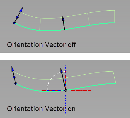
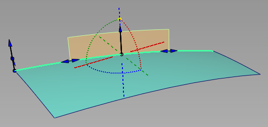
Orientation Vector
Allows you to reorient the flange edges to a vector. Use the Orientation Vector options to select or create a vector or use the manipulator to reorient the edges.
Double Sided
Turn this option on to build draft surfaces on both sides of a curve simultaneously.
Single Surface
This option only appears if Double Sided is on. Turn it on to build only one surface, extending on both sides of the curve.
Intersect Flanges
Select this option to handle corner conditions when two flange or draft surfaces meet. The flanges are extended and trimmed to their intersection so they join properly at corners. You can choose to Trim or Trim Convert the flanges.
Flip
Reverses the direction of the new surface(s).
Explicit Control
Turn on this option if you want to specify the exact degree and maximum number of spans in the new surface(s).
Explicit Control Options
U Degree
Degree of the new surface(s) in the U direction. Enter a whole number from 2 to 9. This option only appears if Explicit Control is checked.
V Degree
Degree of the new surface(s) in the V direction. (The surfaces are always of degree 1 in the V direction.)This option only appears if Explicit Control is checked.
Spans
If Surface Type is set to Multiple surfaces, this value specifies the maximum number of spans for each draft surface. If Surface Type is set to Single surface, it specifies the maximum number of spans for each piece of the original surfaces.
This option only appears if Explicit Control is checked, and Bézier Surfaces is not checked.
Segmentation Option
NURBS – Fits with a non-rational NURBS curve.
Bezier – Fits with a non-rational NURBS curve, then detaches at the spans to produce Bezier segments.
Fitting Method
Surface UV – Follows the U or V parameterization of the underlying surface. If this fails, then the COS is fit using the Curvature method.
Chordal – Fits based on the arc length. Each parameter step corresponds to an equivalent step in 3D. If the Segmentation Option is Bezier, Alias tries to produce equally spaced CVs.
Parameter – Matches the parameterization of the COS.
Curvature – Fits based on the arc length and curvature. Places more CVs in areas of higher curvature.
Blend – A hybrid of the Surface UV and Chordal fitting methods. A UV to Chordal Influence value of 0 is equivalent to using the Surface UV method. A value of 1 is equivalent to using the Chordal method. For values in between, the point distribution is a geometric mean between the two types.
Draft Vector Options
These options only apply when Type is set to Draft.
X,Y, Z
Select one of these to specify a pull direction along that axis.
View
Select this option to specify a pull direction normal to the current view. The vector is not drawn in the view windows.
If the current view is changed, click Refresh View Vector to update the vector.
Picked
Selecting this option lets you specify the name of an existing vector in the Picked Vector field, or pick the vector in the view. This vector defines the pull direction.
Manip
This option is selected automatically when you update the pull direction by manually modifying the manipulator in the view.
Refresh Vector
This button only appears if View is selected. Click it to update the vector if the view has been modified.
Retain Vector
Click this button to create a vector construction object in the view windows. Unless you do this, the vector direction you specified is used by the tool, but you will not see and be able to re-use the vector.
Create Vector
Click this button to create a draft pull direction vector.
Click in the view to place the start of the axis, or type the position and press  . Use the vector manipulator to position the vector and click Accept.
Additional information
When Type is set to Draft in the control window, and Draft Vector Options is set to X, Y, or Z, the tool uses the X, Y, and Z axes from the construction plane, if one is set.
The following rules apply:
- Draft surface direction always respects the current coordinate system.
- If a draft surface was created in one set of coordinates (construction plane), and is later query-edited in a different one, the Refresh Vector button can be clicked to update the draft direction.
Modify Range
Modify Range
When this option is checked on, Start and End sliders appear in the control window, and arrow manipulators appear on the draft surfaces. Drag these arrows to modify the extent of the draft surfaces across the input curves.
When this option is checked off, the draft surfaces extend to the ends of the input curves.
Start/End
Use these sliders to modify the extent of the draft surfaces. Start and End values of 0.0 and 1.0 respectively, define the original extent.
Range of draft surface (in orange) extends from 0.25 (Start) to 0.75 (End).
Surface Structure
Surface Type
If you choose Single surface, a single surface is built. If you choose Multiple surfaces, a separate surface is created for each of the input curves you selected, and the surfaces are grouped.
Creating a single surface might add additional spans.
Bézier Surfaces
This option only appears if Surface Type is set to Multiple surfaces. If it is checked on, each surface will be a Bézier patch.
Bézier patches have a single span, and their maximum degree in the U direction is set through the Explicit Control section. The default is the degree of the input curve.
Pick Mask
These options let you choose what types of curves are selectable as input. This is especially useful when using box selection.
Surface Isoparm
Check this option to make surface isoparms selectable as input.
Surface Trim Edge
Check this option to make surface trim edges selectable as input.
Curve
Check this option to make free curves selectable as input.
This option only appears when Type is set to Draft.
Curve-on-surface
Check this option to make curves-on-surface selectable as input.
Control Options
Auto Update
Turn on this option to have the new surface automatically re-calculated and displayed as you modify the option values or make adjustments to the manipulators.
If it is off, you must click the Update button in the lower right corner of the window to update the surface(s).
If Auto Update is turned off, you can also use the spacebar to click the Update button.
Inter Continuity Check
Checking on this option displays continuity locators between the output surfaces, indicating whether or not they are tangent continuous. Green T locators indicate that the surfaces are tangent continuous while red/yellow T locators indicate they are not.
The Continuity Angle fromPreferences > Construction Options is used when testing for tangent continuity, and a shared boundary is only checked if it doesn't present any gap larger than the Topology Distance tolerance (also found in Construction Options).
Only natural (non-trimmed) edges are checked.
Tangent Angle Maximum
This option is only available when Inter Surface Continuity is checked on. It is used to exclude "corners" from the check. If, at any check point along a shared boundary, the angle between surface normals is larger than this value, then tangent continuity is not reported along that boundary. The default is set to 30.0 degrees.
Create Metadata
Specifies whether or not the Multi-Surface Draft tool creates history metadata.
The Create Metadata option is available only with Autodesk Alias 2019.2 or later.
Continuity Check
Turn on this option to check for positional continuity between the newly created surface(s) and the original surface(s). A green P means positional continuity exists.
Chain Select
If this box is checked, selecting a surface curve also selects all other surface curves that are tangent continuous with it.