Use this procedure to manually add gridlines and specify an offset for each one when you need to create a unique grid that does not fit into any of the other division types. You can also start with a fixed cell dimension grid or a fixed number of cells grid and then manually adjust the gridlines to suit your needs.
- Click
 .
. 
- Expand Architectural Objects Door/Window Assembly Styles. Note: Alternatively, select a door/window assembly in the drawing, and click .

- Select a door/window assembly style.
- Click the Design Rules tab.
- In the left pane, select Divisions under Element Definitions.
- Select a Divisions definition or click
 to create a new one.
 - Select Manual for Division Type.
- Click
 to add a gridline.
 Insert as many grid lines as you need. If you need to remove a grid line, select it from the table, and then click
 .
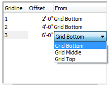
. - Under Offset in the grid line table, specify an offset distance for each grid line.

- Under From in the grid line table, select the grid location from which the grid line is offset.
- Specify an offset distance:
If the orientation is… Then… horizontal specify an offset distance in Bottom Offset or Top Offset. vertical specify an offset distance in Start Offset or End Offset. - Click OK.