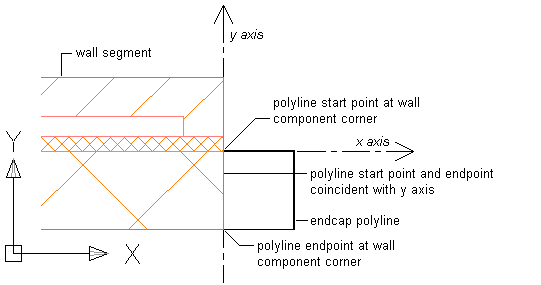
Valid wall endcap polylines start at the wall component corner on the Y axis. Ideally, the polyline ends at the other wall component corner on the Y axis, so that both the polyline start point and endpoint are coincident with the Y axis and both have the same X value as shown.

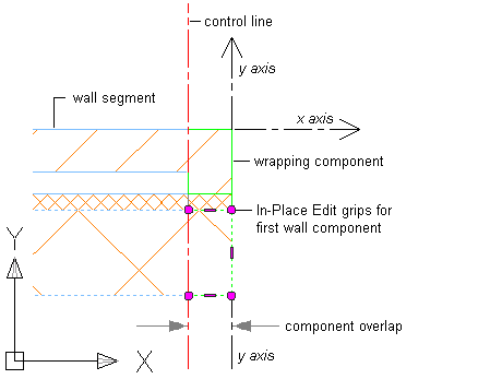
Often you will work with wall styles that have one or more components that wrap at the wall endcap or opening. For example, a brick wall component in some wall styles wraps at the wall endcap. With this condition, a control line parallel to the Y axis delineates the innermost component face, and the remaining components in the wall style will start at this control line. When you select a wall segment in order to apply a new wall endcap condition for the first wall component, the Edit in Place grips display along the control line as shown.

Adding a Wall Endcap Polyline to a Single-Component Wall Segment
- At the end of an existing single-component wall segment in plan view, draw a polyline to define the wall endcap condition.
- Select the wall segment.
- Click

 .
. 
- Select the wall endcap polyline.
- Press Enter to accept the wall component that you want.
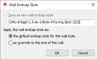
The Wall Endcap Style dialog box displays, in which you can do the following:
- Save the new wall endcap as a new wall endcap style.
- Apply the wall endcap style as a default endcap for this wall style. All existing and new instances of this wall style will display the new wall endcap condition.
- Apply the wall endcap style as an override to the selected end of this wall style. Only this single instance of this wall style will display the new wall endcap condition.
- You can choose to erase or retain the original polyline layout geometry of the wall endcap.

Click OK, and the specified wall component is merged with the wall endcap polyline. Click Cancel to discard your changes.
In the following example, a wall endcap polyline is associated with a wall component.

Use this procedure to associate a wall endcap polyline with the component of a single-component wall segment.
Adding a Wall Endcap Polyline to a Multiple-Component Wall Segment
- On an existing multi-component wall segment in plan view, draw a polyline to define the wall endcap condition.
- Select the wall segment to edit.
- Click

 .
. 
- Select the wall endcap polyline.
The first wall component to which you could associate the polyline is highlighted with a red line inside the perimeter of the wall component.
- Press Enter to accept this wall component, or press Tab to advance to the next wall component.
Continue to press Tab until the component that you want is highlighted.
- Press Enter to accept the wall component that you want.
The Wall Endcap Style dialog box displays, in which you can do the following:
- Save the new wall endcap as a new wall endcap style.
- Apply the wall endcap style as a default endcap for this wall style. All existing and new instances of this wall style will display the new wall endcap condition.
- Apply the wall endcap style as an override to the selected end of this wall style. Only this single instance of this wall style will display the new wall endcap condition.
- You can choose to erase or retain the original polyline layout geometry of the wall endcap.

Click OK, and the specified wall component is merged with the wall endcap polyline. Click Cancel to discard your changes.
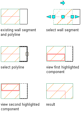
In the following example, a wall endcap polyline is applied to the second of two wall components in a multi-component wall segment.

Use this procedure to associate a wall endcap polyline with a specific component in a multiple-component wall segment.