AutoCAD Architecture 2023 toolset can read and convert the following LandXML data types:
- Parcels
- COGO points
- Surfaces
Parcels
Parcels are two-dimensional shapes created from closed lines, arcs, and polylines. When a parcel is imported, the parcel name and the lines (segments) and curves (arcs) that make up the parcel boundary are used for the conversion.
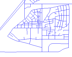
Parcels in a street layout from Autodesk Land Desktop
You can convert parcels to spaces or polylines. When you convert parcels to spaces, you can define a space style that is applied to the spaces generated from the parcels, and the parcel name is used as the space name. When the parcel is converted to a polyline, the parcel name is lost.
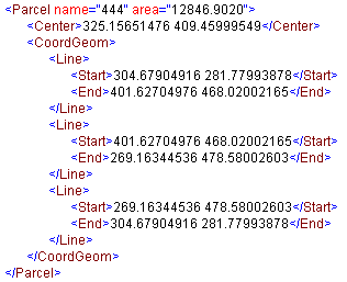
Parcel data in LandXML
COGO (Coordinate Geometry) Points
You can import LandXML COGO (Coordinate Geometry) points and convert them to AutoCAD points.
Civil engineers create COGO points to locate crucial surveying locations. A COGO point can be a project benchmark point - a common datum that the entire civil team works off and from which all critical dimensions are located.
COGO points are the foundation for any civil engineering or surveying project. In Land Desktop, you can use description keys to place points in the drawing with symbols on specific layers. When importing a LandXML file you can map selected points to the appropriate layer.
When a COGO point is imported it is defined by its coordinates in the form of “northing easting” or “northing easting elevation.”
For example, a COGO point could be represented as: <CgPOINT NAME="1" DESC="MYPOINT">248.04605951 359.53997314 1.000000</CgPOINT>.
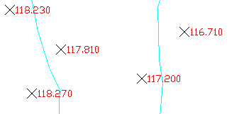
COGO points on a map
Surfaces
In most surveying and civil engineering operations, you gather information about elevations to generate surface contours that represent a model of the ground surface. The surfaces in LandXML are made up of many faces which are either TINs (Triangular Irregulated Networks) or quadrilaterals. Points or contours are usually a primary part of the original surface information and are supplemented with break lines and boundaries. You can create a surface in LandXML, and then import it. It is converted to a Free Form mass element.
In the following cases, importing surfaces can create errors or fail altogether:
- Surfaces with vertical faces
- Surfaces with tiny gaps between the individual faces
- Surfaces with very narrow faces
If the import fails, an error message is displayed on the command line, such as “Failed to create mass element from terrain.”
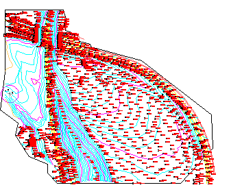
Surface model in Autodesk Land Desktop
A surface model is usually a complex structure with many defining points and faces. When you convert a surface model to a Free Form mass element, the points and faces are merged into one composite mass element body.
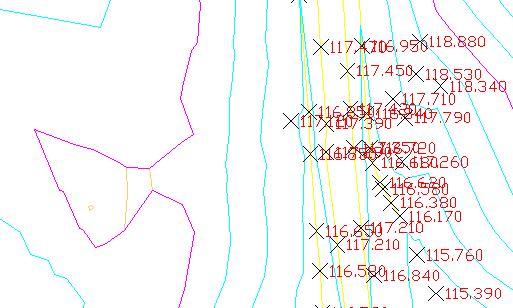
Surface model detail
A Free Form mass element contains a large number of grips. Displaying all grips can slow down the performance and be unnecessary for using the mass element. There are two ways to control the display of grips on mass elements:
- By default, the grips on a Free Form mass element are only displayed if their number does not exceed 2000 grips per element.
- You can turn off the display of grips in the drawing altogether if you click

 Options, then click the Selection tab, and under Grips, clear Enable Grips.
A surface in the LandXML Schema contains information about the surface name, type, 2D and 3D area, and the maximum and minimum elevations. It also contains information about each of the points and faces that comprise the surface. The surface information is merged into one composite mass element body, which can have thousands of faces. Applying a surface hatch or texture map to a complex mass element can be quite time-consuming.
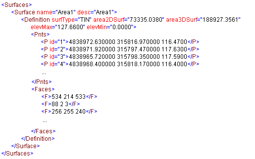
Surface data in LandXML