Customizes the display.
OPTIONS (Command) Find
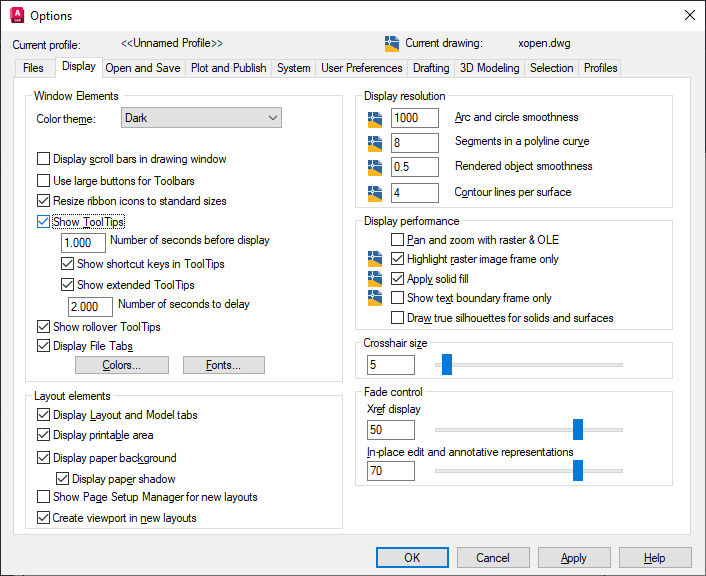
List of Options
The following options are displayed.
Window Elements
Controls display settings specific to the drawing environment.
- Color theme
-
Controls color settings in a dark or light color for interface elements such as the status bar, title bar, ribbon bar, palettes, and the application menu frame. (COLORTHEME system variable)
- Display Scroll Bars in Drawing Window
-
Displays scroll bars at the bottom and right sides of the drawing area.
- Use Large Buttons for Toolbars
-
Displays buttons in a larger format at 32 by 32 pixels.
- Resize Ribbon Icons to Standard Sizes
-
Scales the small ribbon icons to 16 x 16 pixels and the large ribbon icons to 32 x 32 pixels when they do not match the standard icon sizes. (RIBBONICONRESIZE system variable)
- Show Tooltips
-
Controls the display of tooltips on the ribbon, toolbars, and other user interface elements. (TOOLTIPS system variable)
- Number of Seconds Before Display
-
Sets the intial delay time to display tooltips.
- Show Shortcut Keys in Tooltips
-
Displays shortcut keys in the tooltip (Alt + Key) (Ctrl + Key).
- Show Extended Tooltips
-
Controls the display of extended tooltips.
- Number of Seconds to Delay
-
Sets the delay time between the display of basic tooltips and extended tooltips.
- Show Rollover Tooltips
-
Controls the display of rollover tooltips when the cursor hovers over an object. (ROLLOVERTIPS system variable)
- Display File Tabs
-
Displays the File tabs at the top of the drawing area. (FILETAB and FILETABCLOSE commands)
- Colors
-
Displays the Color Options dialog box. Use this dialog box to specify colors of elements in the main application window.
- Fonts
-
Displays the Command Line Window Font dialog box. Use this dialog box to specify the font for the command window text.
Layout Elements
Controls options for existing and new layouts. A layout is a paper space environment in which you can set up drawings for plotting.
- Display Layout and Model Tabs
-
Displays the layout and Model tabs at the bottom of the drawing area. When this option is cleared, the tabs are replaced by buttons on the status bar.
- Display Printable Area
-
Displays the printable area in a layout. The printable area is represented by the area within the dashed line and is determined by the selected output device.
- Display Paper Background
-
Displays a representation of the specified paper size in a layout. The paper size and plot scale determine the size of the paper background.
- Display Paper Shadow
-
Displays a shadow around the paper background in layout. This option is not available if the Display Paper Background option is cleared.
- Show Page Setup Manager for New Layouts
-
Displays the Page Setup Manager the first time you click a layout tab. Use this dialog box to set options related to paper and plot settings.
- Create Viewport in New Layouts
-
Creates a single viewport automatically when you create a new layout.
Crosshair Size
-
Determines the size of the crosshairs as a percentage of the screen size.
( CURSORSIZE system variable)
Display Resolution
Controls the quality of the display of objects. If you set high values to improve display quality, the impact on performance is significant.
- Arc and Circle Smoothness
-
Sets the resolution for objects in the current viewport. (VIEWRES command)
- Segments in a Polyline Curve
-
Sets the number of line segments to be generated for each spline-fit polyline generated by the Spline option of the PEDIT command. (SPLINESEGS system variable)
- Rendered Object Smoothness
-
Not available in AutoCAD LT
Adjusts the smoothness of shaded and rendered objects and objects with hidden lines removed.
Adjusts the smoothness of shaded objects and objects with hidden lines removed. (FACETRES system variable)
- Contour Lines per Surface
-
Not available in AutoCAD LT
Specifies the number of contour lines displayed on the curved surfaces of 3D solids. (ISOLINES system variable)
Display Performance
Controls display settings that affect performance.
- Pan and Zoom with Raster and OLE
-
Not available in AutoCAD LT
Controls the display of raster images and OLE objects during Realtime ZOOM or PAN. (RTDISPLAY system variable)
If dragging display is turned on and you select Pan and Zoom with Raster and OLE, a copy of the object moves with the cursor as you reposition the original. ( DRAGMODE system variable)
- Highlight Raster Image Frame Only
-
Not available in AutoCAD LT
Controls whether the entire raster image or only the raster image frame is highlighted. (IMAGEHLT system variable)
- Apply Solid Fill
-
Specifies whether hatches and fills, 2D solids, and wide polylines are filled in. (FILLMODE system variable)
- Show Text Boundary Frame Only
-
Controls how text is displayed. (QTEXTMODE system variable)
- Draw True Silhouettes for Solids and Surfaces
-
Not available in AutoCAD LT
Controls display of silhouette edges of 3D solid objects in a 2D Wireframe or 3D Wireframe visual style. (DISPSILH system variable)
Fade Control
Controls the fading intensity value for DWG xrefs and, in AutoCAD, reference editing.
- Xref Display
-
Controls the dimming for all DWG xref objects. (XDWGFADECTL system variable)
This option only affects the display on the screen. It does not affect plotting or plot preview.
- In-place Edit and Annotative Representations
-
Not available in AutoCAD LT
Specifies the fading intensity value for objects during in-place reference editing. Objects that are not being edited are displayed at a lesser intensity. (XFADECTL system variable)
With in-place reference editing, you can edit a block reference or external reference from within the current drawing. The valid range is 0 through 90 percent.