Have you ever needed to break an object like a line or arc to create a gap? How about breaking a line or arc at a specific point? Maybe you would like to change part of the linework to a different linetype, color, or layer.
In the past, you might have trimmed the line or arc and drawn a new segment to replace it so you can change the properties of that new segment. There is no need to trim and create a new line or arc segment. Using BREAK or BREAKATPOINT is a more efficient way to break a line or arc at a specific location creating two objects that can each have different properties.
Before You Get Started
There are a couple of things to setup before you get started.
- Make sure the COMMANDPREVIEW system variable is set to 1. With command preview turned on, you see a preview of the results while using a command.
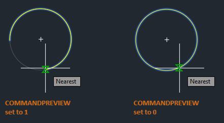
See Have You Tried: Command Preview for more information.
- Click View tab > Palettes panel > Properties.
Find
You can also enter PROPERTIES at the Command prompt.
Breaking a Line to Add a Gap
Let's begin with breaking a single line into two segments with a gap.
- Draw a new line as shown.

- Click Home tab > Modify panel (expanded) > Break.
Find
You can also enter BREAK at the Command prompt.
- Select the object to break.
The point at which you select the object becomes the first break point.

- Specify the second break point.

That's great. You broke a single line into two segments with a gap between the two specified points. These segments are two separate lines that can each have a different color, linetype, or layer.

I'll cover more on that later in this article.
In the previous example, you broke a line into two segment using arbitrary points, but chances are you want to be more precise when specifying points.
Use the following methods for a more precise way to specify the break points on a line.
- Object snaps can be used to precisely locate a point on the line, for example the midpoint.

- Snap mode can be used to specify a point along or near the line.

- Relative coordinates can be used to specify the second point at which to break the object. The example below will create a gap in the line three units to the right.

Breaking a Line at a Point Using BREAK
In the previous example, you used the BREAK command to break a line into two segments with a gap between the two specified points. In the next example, you'll enter @ to break a line into two segments without leaving a gap.
- Draw a new line as shown.
- Click Home tab > Modify panel (expanded) > Break.
Find
You can also enter BREAK at the Command prompt.
- Select the object to break.
The point you select on the object becomes the first break point and the location where the break will occur.
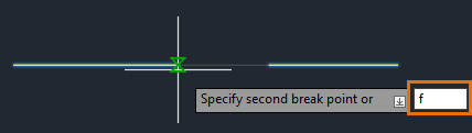
- When prompted for the second break point, enter
F to use the First point option and override the original first point.
- Use the
MIDpoint object snap and specify the first break point as the midpoint of the line.

- For the second break point enter
@.
 @ instructs the BREAK command to use the previous point specified for the second point. In this case, the midpoint of the line is used for the first and second points, resulting in two equal segments without a gap between them.
There's another option for breaking a line into two segments without leaving a gap, the BREAKATPOINT command. The BREAKATPOINT command is available in AutoCAD and AutoCAD LT 2021 and later. I'll cover the BREAKATPOINT command later in this article.
Breaking a Circle
Some of the same techniques for breaking a line can be used to break a circle. Keep in mind that for some modify commands like BREAK, are affected by the order in which you select objects or specify points.
- Draw a new circle as shown.

- Click Home tab > Modify panel (expanded) > Break.
Find
You can also enter BREAK at the Command prompt.
- Select the circle to break.
The point you select on the object becomes the first break point.

- When prompted for the second break point, enter
F to use the First point option and override the original first point.

- Use the
QUADrant object snap and specify the first break point as the quadrant of the circle.

- Use the
QUADrant object snap again and specify the second break point.
 Using the BREAK command and the Quadrant object snap, you can break and remove half of the circle.

Break a Line at a Specified Point
Earlier in this article, I explained how to break a line at a specific point by entering @ for the second point. Now let's use the BREAKATPOINT command to break a line at a specified point without leaving a gap.
Let's say, I want to make two existing lines the same length and then use the new segment to close off one of the ends of the horizontal lines.

- Draw two new lines as shown.

- Click Home tab > Modify panel (expanded) > Break at Point.
Find
You can also enter BREAKATPOINT at the Command prompt.
- Select the bottom line to break.

- Turn object snap tracking on from the status bar Find or by pressing the F11 Shortcut Key.
- Hover over the endpoint of the top line to acquire the point. Drag the cursor up or down and click the left mouse button to specify the break point.
The line will break at the intersection of the object snap tracking line and the bottom line. To learn more about object snap tracking, see Object Snap Tracking in the Hitchhiker's Guide.

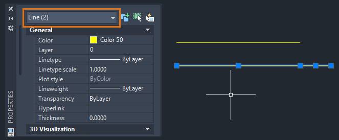
- To verify the line has been broken into two segments, open the Properties palette and select both lines. Click View tab > Palettes panel > Properties.
Find
You will see Line (2) displayed in the Object Type drop-down list at the top of the Properties palette.
- Select the short line segment as shown below and select the far-right grip.

- Stretch the end of the bottom line to the endpoint of the top line.

To learn more techniques about working with grips, see Have You Tried: Just Grip It!.
With the stretch complete, you should have a vertical line that is perpendicular between the top and bottom lines.
Break a Line and Change its Layer
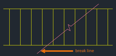
Because the vertical lines are single line objects, first you need to break them at a specific point before you can change the layer. You can use the intersection of the break line and the vertical lines as the break location.
- Draw the example below.
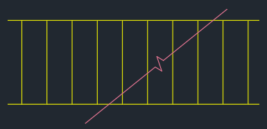
Create a new layer called hidden with the following properties:
- Color: Cyan
-
Linetype: Hidden
To learn more about layers, see Layers in the Hitchhiker's Guide.
- Depending on your AutoCAD release do one of the following:
- AutoCAD and AutoCAD LT 2021 and Later
-
- Click Home tab > Modify panel (expanded) > Break at Point. Find
- Select the object to break.

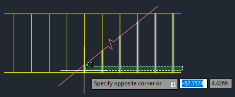
- Using the
INTersection object snap, select the intersection of the break line and the vertical line.
 The vertical line has been broken at the intersection.
- AutoCAD and AutoCAD LT 2020 and Earlier
-
- Click Home tab > Modify panel (expanded) > Break. Find
- Select the object to break.
- When prompted for the second break point, enter F to use the First point option and override the original first point.
- Using the INTersection object snap, select the intersection of the break line and the vertical line.
- For the second break point enter
@.
The vertical line has been broken at the intersection.
- Do the same for the remaining lines.

- Using a crossing window, select the six lines to the right of the break line and change the layer to
hidden.
 Using the BREAKATPOINT command or entering @ for the second point are efficient ways to break a line or arc at a specific location without leaving a gap.
Summary
I hope this helped give you a better understanding of the BREAK and BREAKATPOINT commands. With the ease of use and flexibility offered by these commands, I'm sure you will be able to put them to work for you.
Related Have You Tried Articles
- Have You Tried: Just Grip It! - Stretch, move, copy, rotate, scale, and mirror objects using grips.
- Have You Tried: Command Preview - Temporarily displays the possible outcome of the active editing command before completing the command.
Break Object Related Commands and System Variables
Here are some frequently used commands and system variables related to breaking linear and curved objects.
| Command | Description |
|---|---|
| BREAK | Breaks the selected object between two points. |
| BREAKATPOINT | Breaks the selected object into two objects at a specified point.
Note: The BREAKATPOINT command is available in AutoCAD and AutoCAD LT 2021 and later. If you are using an earlier release, entering @ for the second point of the BREAK command will give you the same result.
|
| System Variable | Description | Default Value | Saved in |
|---|---|---|---|
| COMMANDPREVIEW | Controls whether a preview of the possible outcome of certain commands is displayed. | 1 | Registry |