Layers are fundamental to organizing and controlling the appearance of geometry and annotation in a drawing. Chances are, you have worked on drawings with various layer standards that don't match those of your company. When this happens, it can make working on those drawings tough at times, especially when needing to share and plot those drawings.
AutoCAD provides several tools to help you cleanup both used and unused layers in your drawings:
- Layer Walk – Views all the objects on each layer, one layer at a time
- Layer Merge – Moves all objects on specified layers to a single target layer, and purges the specified layers from a drawing
- Layer Delete – Deletes all objects on a specific layer
- Purge – Removes unused layers and other named objects from a drawing
Note: The Purge feature isn't covered in this article. For information on using Purge, see Have You Tried: Purge and Overkill.
- Layer Translator (AutoCAD only) – Updates and merges layers based on a layer translation map
Tip: Layer Names Not Sorting Alphabetically
A drawing can contain hundreds or even thousands of layers. When a drawing contains a large number of layers, you might notice that the layers in the Layer drop-down list of the Quick Access toolbar, ribbon, or lists in dialog boxes are not sorted alphabetically. This sorting limitation is likely related to the current value of the MAXSORT system variable. The MAXSORT system variable controls the maximum number of items that AutoCAD sorts alphabetically in a list. Increasing the value of MAXSORT should resolve the alphabetical sorting of items in lists.
View Objects Layer by Layer
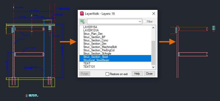
Working on an existing drawing for the first time, especially one from outside your company, can be challenging as companies often follow their own internal layer standards. The Layer Walk feature (LAYWALK command) allows you to see the objects on each layer in the current drawing. As you select layers, the objects on those layers are visible while objects on all other layers are temporarily hidden.
The following steps explain how to use Layer Walk:
- Open the Section1.dwg sample drawing from the C:\Program Files\Autodesk\AutoCAD <release>\Sample\Sheet Sets\Architectural\Res folder. If you want, you could also open one of your drawing files, just update the steps accordingly.
- Click Home tab > Layers panel (expanded) > Layer Walk. Find
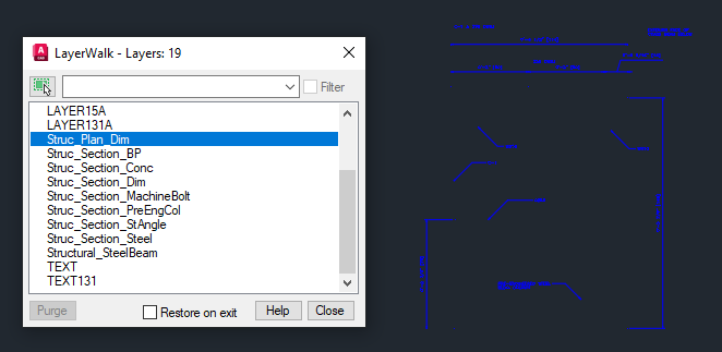
- In the LayerWalk dialog box, select
Struc_Plan_Dim from the list.
Notice that only the geometry assigned to that layer is displayed.
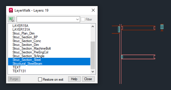
- Press the Down Arrow key until you reach Structural_SteelBeam.
Notice each time you press the Down Arrow key, AutoCAD changes the visibility of the selected layer to on and the other layers to off.
- More than one layer can be selected at a time by holding the Ctrl key and selecting the layers to be viewed. Hold down the Ctrl key and select
Struc_Section_Steel.
The objects on the Struc_Section_Steel and Structural_SteelBeam layers are now both visible. If you want to select a range of layers, hold down the Shift key and select the first and last layer in the range. All layers in between are selected and are now visible.
- Clear the Restore on Exit checkbox.
When Restore on Exit is cleared, the selected layers remain visible in the drawing when you close the dialog box. If Restore on Exit is selected, the layers in the drawing are restored to their state before Layer Walk was used.
- Click Close.
- If the Layer – Layer State Changes message box is displayed, click Continue.
Notice that only the Struc_Section_Steel and Structural_SteelBeam layers are visible in the drawing.
- Now with the drawing being less complex, you can make your edits and then return to the previous layer state by clicking Home tab > Layers panel (expanded) > Previous.
Find
Note: If you made other changes to layers since using Layer Walk, you may need to click Previous multiple times to get back to the layer state before using Layer Walk. Clicking Previous multiple times could cause other layer changes to be undone as well, such as turning on/off layers or even reverting a recent color change. One solution to this is to create a named layer state with the Layer State Manager (LAYERSTATE command) before using Layer Walk, and only storing the On/Off and Freeze/Thaw properties of the layer state. For more information on layer states, see Have You Tried: Layer States.
Merge Layers
As you work on a drawing, there will be times when you need to update the layers in a drawing to a new set of standards or simplify the layer organization of a drawing by reducing the number of layers used. The Layer Merge feature (LAYMRG command) allows you to move all objects from one or more selected layers to a target layer. The unused layers are automatically purged.
The following steps explain how to merge layers in a drawing:
- Open the Section1.dwg sample drawing from the C:\Program Files\Autodesk\AutoCAD <release>\Sample\Sheet Sets\Architectural\Res folder. If you want, you could also open one of your drawing files, just update the steps accordingly.
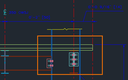
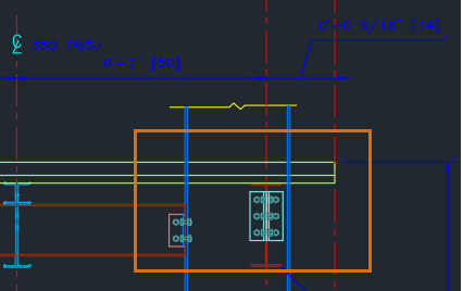
- Zoom in on the upper-right area of the section view so you can see the fasteners on the steel beams.
The fasteners are on two different layers, C-241-1 and Struc_Section_MachineBolt. We want to take the objects on layer C-241-1 and merge them with the Struc_Section_MachineBolt layer.
- Click Home tab > Layers panel (expanded) > Merge. Find
- At the Select object on layer to merge or [Name]: prompt, enter
N to select the layer to merge from a dialog box.
You could also select an object on the layer you want to merge as well.
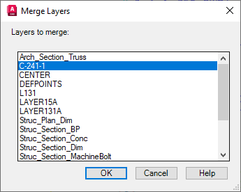
- In the Merge Layers dialog box, select
C-241-1 from the list and click OK.
- Optionally, select additional layers to merge.
- Press Enter to complete the selection of layers to merge.
- At the Select object on target layer or [Name]: prompt, enter N.
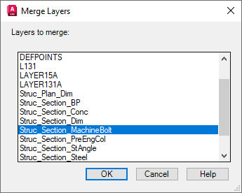
- In the Merge Layers dialog box, select
Struc_Section_MachineBolt from the list and click OK.
- In the Merge to Layer message box, click Yes to continue.
The objects on the C-241-1 layer are merged with the Struc_Section_MachineBolt layer, and the C-241-1 layer is purged from the drawing.
Delete All Objects on a Layer
From time to time, you might want to delete all objects on specific layers. This can be beneficial to reduce the size of a drawing file or simplify the complexity of a model. Maybe you only need a general representation of a design when sharing it with others, such as a building outline to reference. The Layer Delete feature (LAYDEL command) allows you to erase all objects on a layer and then purge that layer from the drawing.
The following steps explain how to remove all objects on a layer and then purge that layer from a drawing:
- Open the
A-03.dwg sample drawing from the
C:\Program Files\Autodesk\AutoCAD <release>\Sample\Sheet Sets\Architectural folder. If you want, you could also open one of your drawing files, just update the steps accordingly.
Tip: Before erasing all objects on and then purging a layer, you could use Layer Walk (LAYWALK command) to see what is on each layer first and isolate just the layers you want to delete. If you clear the Restore on Exit option in the Layer Walk dialog box, the objects on the selected layers remain visible upon closing the dialog box.
- Click Home tab > Layers panel (expanded) > Delete. Find
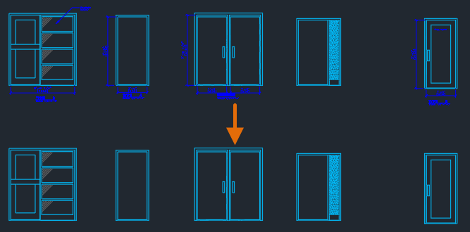
- At the Select object on layer to delete or [Name]: prompt, select the annotation, leader, and dimensions in the drawing.
- Press Enter to delete the objects and purge the selected layers.
- At the Do you wish to continue? [Yes/No] <No>: prompt, enter Y to continue.
Translate Layers (AutoCAD Only)
Updating the layers in a drawing from one standard to another can take some time, but what if you have a set of hundreds or even thousands of drawings that need to be updated? While you could use the Layer Merge feature along with the Layer Properties Manager to manually update your layers, that can be inefficient and could result in inconsistencies.
The Layer Translator (LAYTRANS command), available only in AutoCAD, allows you to create a layer mapping. A layer mapping is a relationship between layers in a drawing to those of a defined set of standards. You can use a layer mapping to:
- Merge one or more layers
- Map two layers with different names which effectively renames one layer
- Map layers with the same names to update layer properties
The following steps explain how to create and use a layer translation map to cleanup layers in a drawing:
- Open the Section1.dwg sample drawing from the C:\Program Files\Autodesk\AutoCAD <release>\Sample\Sheet Sets\Architectural\Res folder.
- Click Manage tab > CAD Standards panel > Layer Translator. Find
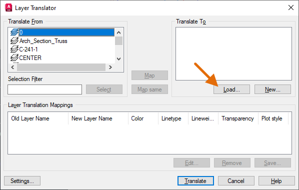
- In the Layer Translator dialog box, click Load under the Translate To section.
The Load button allows you to select the drawing that contains the layers you want to use in updating the layers in the current drawing, typically, this can be a Drawing Template (DWT) or Drawing Standards (DWS) file. You can also select a drawing file that contains a previously saved layer translation mapping.
- In the Select Drawing File dialog box, browse to the C:\Program Files\Autodesk\AutoCAD <release>\Sample\Sheet Sets\Architectural\Res folder and select Section2.dwg. Click Open.
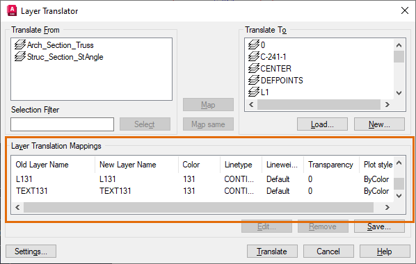
- In the center of the dialog box, click Map Same.
All layers with the same names between the two drawings are added to the Layer Translation Mappings section near the bottom of the dialog box. You should now be left with two layers that are not mapped.
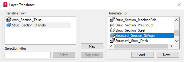
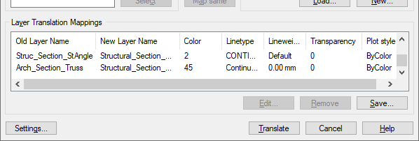
- In the Translate From list, select
Struc_Section_stAngle and then select
Structural_Section_StAngle from the Translate To list. Click Map.
Not every layer we want to use was defined in the loaded drawing. We can add a new layer to map the Arch_Section_Truss layer.
- Click New under the Translate To section.
- In the New Layer dialog box, in the Name text box, enter the name
Structural_Section_Truss.
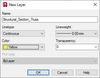
- Click the Color drop-down list and select Choose Color.
- In the Select Color dialog box, select color swatch 45 and click OK.
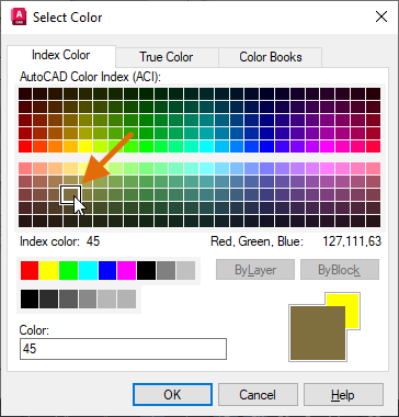
- In the New Layer dialog box, click OK.
- In the Translate From list, select
Arch_Section_Truss and then select
Structural_Section_Truss from the Translate To section. Click Map.
All layers are now mapped.
Based on the source of the imported layers, you might need to make some adjustments to the properties of the layers. You can edit the properties of a layer in the mapping by clicking the Edit button.
Here we will edit the properties of two mapping layers:
- In the Layer Translation Mappings section, select
Struc_Section_Dim in the Old Layer Name column and click Edit.
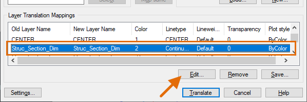
- In the Edit Layer dialog box, change the layer's color to 45 and click OK.
- Change the color of the Structural_Section_StAngle layer to 5.
Now with all the layers mapped, you can optionally save the layer mappings and translate the layers in the drawing.
- Optionally, click Save to save the layer mapping to a drawing file so it can be used to translate the layers in another drawing. Specify a location for the file and click Save to return to the Layer Translator dialog box.
You can then edit and load the layers and the layer mapping saved to drawing file instead of loading Section2.dwg which we did earlier in this exercise.
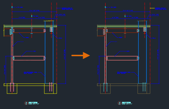
- Click Translate to translate the layers in the
Section1.dwg based on the layer mapping you created.
Automating Drawing and Layer Cleanup
Often, if you are cleaning up layers in one drawing, there is a pretty good chance you might have to perform the same or similar steps in another drawing. You can create a script file or AutoLISP program, to automate the following cleanup operations mentioned in this drawing:
- Renaming layers and modifying the properties of layers with the -LAYER command
- Merging of layers with the -LAYMRG command
- Deleting objects and purging layers with the -LAYDEL command
- Purging layers that are not being used with the -PURGE command
For information on script files and AutoLISP, see Have You Tried: Streamline Tasks with Scripts and the Getting Started tutorials for AutoLISP.
Summary
Working on a drawing with an unfamiliar layer standard or even one in which the layer standards need to be updated can be a challenge. Hopefully, the commands and tips in this article can help you become more efficient in understanding, cleaning up, and updating the layer standards in a drawing.
Layer Cleanup Related Commands and System Variables
Here are some frequently used commands and system variables related to cleaning up layers in a drawing.
| Command | Description |
|---|---|
| LAYDEL | Deletes all objects on a layer and purges the layer. |
| LAYER | Manages layers and layer properties. |
| LAYERSTATE | Saves, restores, and manages sets of layer settings that are called layer states. |
| LAYMRG | Merges selected layers into a target layer, removing them from the drawing. |
| LAYTRANS | Translates the layers in the current drawing to specified layer standards. (AutoCAD Only) |
| LAYWALK | Displays objects on selected layers and hides objects on all other layers. |
| PURGE | Removes unused items, such as block definitions and layers, from the drawing. |
| System Variable | Description | Default Value | Saved in |
|---|---|---|---|
| MAXSORT | Sets the maximum number of items such as file names, layer names, and block names that are sorted alphabetically in dialog boxes, drop-down lists, and palettes. | 1000 | Registry |
| SHOWLAYERUSAGE | Displays icons in the Layer Properties Manager to indicate whether layers are in use. | 0 | Registry |