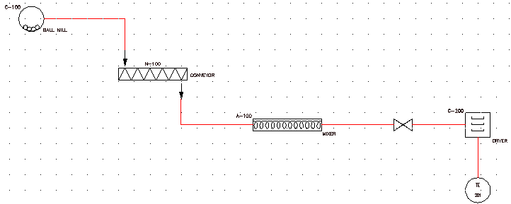
Use the Insert Wire tool to insert lines that represent pipes on a P&ID diagram.
In AutoCAD Electrical toolset, different types of wires represent the type of running pipes that allow water or oil flows from one instrument to another.
Insert wires as pipes
- Click
 . Find
- Change the wire type to RED_25:
Specify wire start or [wireType/X=show connections]:
Enter T, pressENTER
Select the wire layer RED_25. Click OK.
- Connect the pipes as shown. Right-click to exit the command.
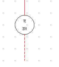
- Click
. Find
- Respond to the prompts as follows:
Specify wire start or [wireType/X=show connections]:
Enter T, pressENTER
Select the wire layer RED_10. Click OK.
Select the bottom of the discrete instrument
Specify wire end or [Continue]:
Drag the wire down a few spaces, press ENTER
- Click
 . Find
- In the Insert Component: Piping and Instrumentation Symbols dialog box, click Flow Arrows.

- In the PID: Equipment dialog box, click Flow Arrow Down.

- Respond to the prompts as follows:
Specify insertion point:
Select to place the flow arrow at the bottom of the new wire
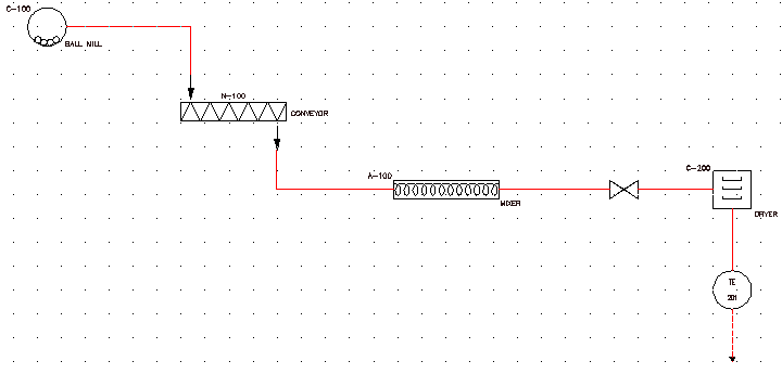
The P&ID diagram is complete.
If you want to see how to expand the P&ID drawing, refer to the P&ID demo drawing file (Demo01.dwg) in the Extra Library Demo project.