Add the title block, set drawing properties, and define wire layers while creating a drawing template.
A drawing template file is used to provide consistency in the drawings that you create by providing standard styles and settings.
When a drawing template file is used to start a new drawing it can:
- Predefine AutoCAD Electrical toolset drawing properties such as component tagging, wire numbering format, and so on.
- Predefine layers and layer properties.
- Predefine wire layers.
- Provide your drawing border and title block.
By default, drawing template files are stored in the template folder, where they are easily accessible.
- Enter QNEW at the command prompt to start a new drawing.
- Select the acad.dwt template.
- Click Open.
- Enter INSERT at the command prompt.
- Click Browse.
- Navigate to and select the title block ACADE_TITLE.DWG created for the border.
- Click Open.
- On the Insert dialog box, make sure the Explode option is not checked.
- Click OK.
- Specify the insertion point at 0,0,0.
- If prompted for attribute values, leave them blank.
Note:
Attributes are invisible if no default values are assigned.
-
Click
 . Find
The alert displays.
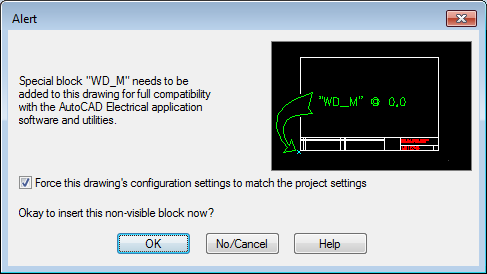
- Click OK to insert the WD_M block.
- Set the default drawing properties such as component tagging, wire numbering, cross-referencing, and so on.
Note:
No specific changes are needed for this tutorial.
- Click OK.
-
Click
. Find
- Add wire layers as needed. Set the properties, color, linetype, and lineweight for each layer. For example:
- In the Create/Edit Wire Type dialog box, click inside the Wire Color column for a blank row and enter RED for a new wire layer.
- Click inside the Size column and enter
12 for the size.
The Layer Name RED_12 is automatically created.
- Click Color.
- Select Red and click OK.
- Click OK.
The layer is created and defined as a wire layer.
- Enter SAVEAS at the command prompt.
- Set the file type as AutoCAD Drawing Template (*.dwt).
- Enter the file name, AEGS_ELECTRICAL.
- Click Save.
The Template Options dialog box displays.
- Select OK.
- Close the drawing, AEGS_ELECTRICAL.DWT.