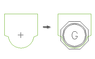
You can insert smart footprint outlines of electrical components and devices onto layout drawings. You pick the insertion point and orientation for the footprint. Assign values on the footprint such as tag, catalog assignment, location, installation, descriptions, ratings, and miscellaneous values.

Insert from Icon Menu
Select an icon picture or the component type from the Menu tree structure. The main menu in the tree structure is displayed as the menu heading just above the menu tree structure.
This icon menu can be modified, expanded, or replaced with your own custom menu. You can change the default icon menu using the Library and Icon Menu Paths section of the Project properties: project settings tab. Use the Icon Menu Wizard to modify the menu easily. The default icon menu can also be redefined in "wd.env". Add entry "WD_MENU" for schematic icon menu and "WD_PMENU" for panel layout icon menu.
Pick a general component category from a generic icon menu (such as pilot lights). Once a component is selected, choose from the options available to insert the footprint.
- Choice A - make catalog assignment for automatic footprint selection. AutoCAD Electrical toolset finds a match for the manufacturer and catalog number combination in the footprint look-up file to determine the correct footprint block to insert.
- Choice B - manual footprint selection or creation.
- Choice C - in cases where a manufacturer and catalog is given but is not in a lookup file, AutoCAD Electrical toolset enables this option allowing you to add an entry in the footprint look-up database file.
Insert a Copy
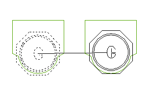
Use the Copy Footprint tool instead of AutoCAD Copy when a panel component footprint has a balloon or a nameplate associated with it. The program establishes invisible Xdata pointers tied to a footprint, and updates them in the Copy Footprint operation.

Insert Manually
Select to use a generic marker only, draw shapes, select a similar footprint, choose from a file dialog box, or pick on an existing block on the current drawing to convert it to AutoCAD Electrical toolset on the fly.
Insert Components and Terminals from Schematic List
Schematic diagrams can help drive the panel layout. Each electrical component carries manufacturer and catalog data with catalog number information. A matching manufacturer and catalog number combination in the footprint look-up file determines the correct footprint block to insert. The list of schematic components checks off the panel footprints you insert.
If you start with panel layouts before you create schematics, schematic pick list data is not available to automate footprint selection and annotation. If you list your panel components in a spreadsheet and in a format that AutoCAD Electrical toolset expects, this spreadsheet data can become your schematic pick list data for panel layout.
Component spreadsheet data format
The spreadsheet data must be in this order and have 28 columns of data and be saved in a "CSV comma delimited" text format. Most of the fields can be left blank:
|
1 |
TAG |
Component tag id (ex: "PB101") |
|
2 |
INST |
Optional installation code |
|
3 |
LOC |
Optional location code |
|
4 |
MOUNT |
Optional mount code |
|
5 |
GROUPWIDTH |
Optional group code |
|
6 |
MFG |
Manufacturer code |
|
7 |
CAT |
Catalog number |
|
8 |
ASM |
Optional catalog assembly code |
|
9 |
CNT |
Optional count value |
|
10 |
UM |
Optional unit of measure |
|
11-13 |
DESC1-DESC3 |
Three lines of description text |
|
14 |
BLKNAM |
Schematic block name (used to determine catalog lookup table name) |
|
15-26 |
RATING1-12 |
Optional rating values |
|
27 |
ITEM |
Optional item number assignment |
|
28 |
(blank) |
Panel terminals spreadsheet data format
The spreadsheet data for panel terminals must be in this order and have 30 columns of data and be saved in a "CSV comma delimited" text format. Most of the fields can be left blank:
|
1 |
TAGSTRIP |
Terminal strip tag id (ex: "TB1") |
|
2 |
INST |
Optional installation code |
|
3 |
LOC |
Optional location code |
|
4 |
MOUNT |
Optional mount code |
|
5 |
GROUPWIDTH |
Optional group code |
|
6 |
MFG |
Manufacturer code |
|
7 |
CAT |
Catalog number |
|
8 |
ASM |
Optional catalog assembly code |
|
9 |
CNT |
Optional count value |
|
10 |
UM |
Optional unit of measure |
|
11-13 |
DESC1-DESC3 |
Optional description text |
|
14 |
BLOCK |
Optional schematic block name (blank) |
|
15-26 |
RATING1-12 |
Optional rating values |
|
27 |
ITEM |
Optional item number assignment |
|
28 |
TERMNO |
Terminal number |
|
29 |
(blank) |
|
|
30 |
WIRENO |
Optional wire number tied to terminal |
Schematic spreadsheet data of previous project
If your new project is like a previous project, you can use the schematics of the previous project to create a component or terminal spreadsheet listing. It can then help drive the new panel layout of the project.
Open the previous project in AutoCAD Electrical toolset. From the Panel Layout menu, select Insert Footprint (Schematic List) or Insert Terminal (Schematic List). On the selection dialog box, check the Save List to External File option and then extract from the project. AutoCAD Electrical toolset creates a comma-delimited file of the schematic data. You can then display this data in spreadsheet format (open it in comma-delimited "CSV" format), edit, and then save back out. Now follow the procedure described for picking and inserting the panel component or terminal footprints from the spreadsheet driven pick list.
Insert from Vendor Menu
Pick the item from a vendor icon menu that is preset with specific catalog number data and footprint block names. Choosing from this menu supplies AutoCAD Electrical toolset with the manufacturer and catalog information and the footprint block name, bypassing any look-up.
It can save time if you frequently use the same vendor and panel components. You can apply this method to create client-specific menus making it easier to use the vendor or components that each client prefers.
Insert from Equipment List
This tool lists data extracted from your equipment list, finds the appropriate panel symbol by querying the footprint_lookup.mdb, and inserts the panel footprint at your pick point. Each line or record in the equipment list represents a single entry into the Panel Equipment in {file name} dialog box for schematic component selection. The quantity for a selected catalog number is not supported.
Insert from User-Defined Pick List
Insert a panel symbol by choosing a catalog number or a component description from a user-defined pick list. The data displayed in this pick list is stored in a database in generic Access format. The file name is wd_picklist.mdb and can be edited with Access or from Add/Edit/Delete along the bottom of the dialog box of the pick list.