You use routing preferences to draw accurate pipe systems in auto layout. Pipe routing preferences specify which pipe part to insert as you lay out the pipe run. Couplings are inserted at the proper pipe length and at break points in the pipe run. Routing preferences meet design standards and specifications and contain the pipe parts (pipes and fittings) used to lay out your pipe run.
- In the Styles Browser palette
 Object Type Piping Objects Pipe Part Routing Preferences
- Select a pipe in the drawing, in the Properties palette Basic Dimensions Routing Preference click

A pipe part routing preference includes one or more size ranges for pipe parts and fittings, such as elbows, tees, laterals, and transitions. The software organizes the size ranges based on nominal pipe diameters. You can use pipe parts and fittings in a specified size range as you lay out the pipe run. The following example shows the routing preferences for Glued. Notice that the available Pipe parts are organized based on material type for US Imperial and US Metric profiles.
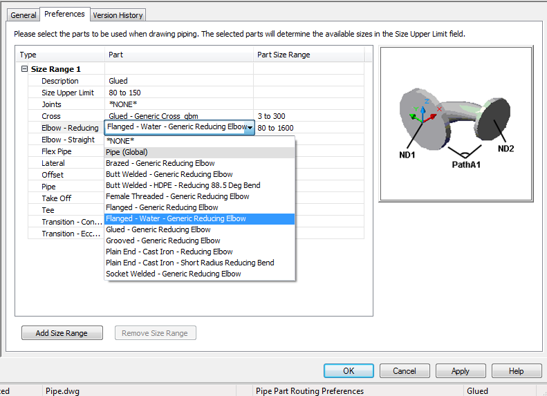
Routing preferences, showing parts organized based on material type
Multiple size ranges provide more flexibility in your piping designs. For example, assume a design specification for a chilled water system requires commercial steel pipe with threaded connections for all pipe sizes 3'' and lower. The system also specifies commercial steel pipe with 150 class, weld neck, flange connections for pipe sizes 3 1/2'' and higher.
When you configure a routing preference for a particular specification, the appropriate fittings are automatically inserted into the piping layout. Auto layout can generate different routing solutions, and prompts you to select the best alternative.

Pipe run drawn using a particular routing preference (Top view, Mechanical - Pipe by Size display configuration)
Pressure Pipes and Gravity Pipes
AutoCAD MEP 2023 toolset includes routing preferences for pressure pipes (horizontal or vertical piping designs) and gravity pipes (sloped piping). For example, the software inserts laterals or angled tees, when appropriate, in auto layout. The following lists a sampling of each:
Pressure pipe (US Imperial profile):
- Butt welded
- Grooved and threaded
- Slip on flanged - 150 lb. and threaded
- Threaded 2000 lb.
Gravity pipe (US Imperial):
- Cast Iron soil pipe (bell and spigot)
- Cast Iron soil pipe (no hub)
- Duct iron mechanical joint
- High-density polyethelene (HDPE)
- Sanitary drain, waste, vent
Size Ranges in Routing Preferences
Pipes and fittings in a size range must have common nominal sizes in a routing preference that you can use in a pipe run. The following conditions apply to size ranges:
- The lower limit of a size range (shown in Size Upper Limit) is set to the smallest size in common with all the selected parts. However, if you create a size value for a mid-size range that is less than the higher limit of the previous size range, the mid-size range value automatically moves to the previous size range. For example, if you set a value of 3 in size range 2, but that value is less than what is in size range 1, size range 2 becomes size range 1 and size range 1 becomes size range 2.
- The list of available sizes for the upper limit of the size range (Size Upper Limit) is filtered to include only the sizes that are common to all of the selected parts.
- The available range of sizes for the selected part is displayed for the part.
For example, when creating a routing preference, you select a pipe with sizes that range from 1/8” to 60” and an elbow with sizes that range from 1” to 24”. Because the lower limit of the size range is set to 1”, you can select an upper limit as high as 24”.
Size range details appear on the Properties palette when you add a pipe segment to a pipe run. The nominal sizes are grouped based on the size ranges for the selected routing preference.