When you are drawing in orthographic mode, you add schematic lines in the world coordinate system (WCS). In the WCS, the X axis is horizontal, the Y axis is vertical, and the Z axis is perpendicular to the XY plane.
You can use the compass to guide your placement of lines. You can also use the AutoCAD® Ortho mode to restrict the cursor movement to the horizontal or vertical axes. The orthogonal alignment depends on the current grid and snap settings. You can turn these tools on or off at any time.
To add schematic lines in orthographic mode
- In the Schematic workspace, start the add command by doing one of the following:
- Open a schematic tool palette, and select a schematic line tool.
If necessary, scroll to display the tool. Because tools contain pre-configured properties for the objects they create, you might not need or be able to specify some of the schematic line properties referenced in this procedure.
-
Click

 .
.
- Enter slineadd.
Note: On the Properties palette, indicates a property is available only when you are adding schematic lines, not when you are modifying them.
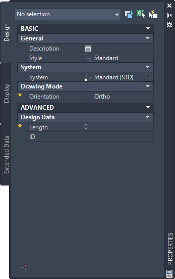
- Open a schematic tool palette, and select a schematic line tool.
- Expand Basic, and for Description, click
 , enter a description for the schematic line, and click OK.
 - For Style, select a schematic line style.
You can select from the styles in the current drawing.
- If you want to change the current system, for System, select the system to which the schematic line belongs.
You can select from the systems in the current drawing.
Tip: You can create schematic line tools that reference styles and systems in content libraries (DWG files). - For Orientation, select Ortho.
- Expand Advanced, and for ID, select or enter an ID designation.
The currently selected schematic line style determines the list of available IDs.
- In the drawing, specify the start point for the line, or use schematic AutoCAD MEP 2023 toolset snaps to connect the line to a symbol or another line.
- Continue to specify points to draw the schematic line.
- If necessary, on the Properties palette, modify the schematic line properties, and add additional lines.
- Press Enter to end the add command.