You can move a schematic line by
- Selecting a grip and dragging it to a new location
- Using the AutoCAD® MOVE command
- Entering new coordinate values for the insertion point of the line using the Properties palette. You can also use the palette to change the normal or the angle of rotation, as described later in this section.
When you move a schematic line, in-line schematic symbols that are anchored to the line are moved along the line.
To move a schematic line in orthographic mode using grips
- Select the line.
- Click the Location grip
 .
. - Move the line:
If you want to… then… use the grip point as the base point for the move drag the line to a new location, and click. specify a base point, and then specify a second point enter b (base point), specify the base point, and then specify the second point. If the schematic line segment is not connected to another object, you can change both its length and angle using the Start grip or End grip. The Start grip and End grip only appear on the schematic line in orthographic mode.
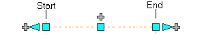
The Start and End grips enable you to change the XYZ location of the start point or end point of the segment. This is useful when you are initially designing runs because you can easily connect a segment to an existing run.
To move a schematic line in isometric mode using grips
- Select the line.
- Click the Move Isoplane grip
 .
. - Move the line:
If you want to… then… use the grip point as the base point for the move drag the line to a new location, and click. specify a base point, and then specify a second point enter b (base point), specify the base point, and then specify the second point.
In isometric mode, the Move Isoplane grip will move the schematic line in the direction which is perpendicular to the plane in which the schematic line lies.
To move or rotate a schematic line using coordinate values
- Select the schematic line.
- On the Properties palette, expand Basic. Under Location, click
 Additional information for the Location worksheet.
- Specify the new location for the schematic line:
If you want to… then… relocate the schematic line enter new coordinate values under Insertion Point. locate the schematic line on the XY plane make the normal of the schematic line parallel to the Z axis: under Normal, enter 1 for Z, and enter 0 for X and Y. locate the schematic line on the YZ plane make the normal of the schematic line parallel to the X axis: under Normal, enter 1 for X, and enter 0 for Y and Z. locate the schematic line on the XZ plane make the normal of the schematic line parallel to the Y axis: under Normal, enter 1 for Y, and enter 0 for X and Z. change the rotation of the schematic line under Rotation, enter a new value for Angle. - Click OK, and press Esc.
A schematic line has an orientation with respect to the world coordinate system (WCS) or the current user coordinate system (UCS). For example, if the schematic line is parallel to the XY plane, then its normal, or perpendicular, plane is parallel to the Z axis. You can change the orientation of the schematic line by aligning its normal with another axis, such as an isometric axis. You can also rotate the schematic line on its plane by changing the rotation angle.