Use this procedure to create a 2D schematic symbol for a block-based MvPart. You can use any drawing command to make the geometry for the block. It is recommended that all geometry be created using base AutoCAD® entities such as lines, polylines, or circles.
To ensure correct display control of your symbol when added to your drawings, draw all geometry for the symbol on layer 0. Assign BYBLOCK for color and linetype, and BYLAYER for lineweight.
- Click

 , and draw the symbol view of the part.
 The symbol block is used as a 2D representation of the part size; therefore, it is recommended that the symbol block be drawn to represent the 2D symbol of the modeled object in plan view.
- Verify that the geometry for the symbol is drawn on layer 0 and is assigned BYBLOCK for color and linetype, and BYLAYER for lineweight. This helps to ensure display control for the part size.
- Click
.

The Block Definition dialog is displayed.
- In the Block Definition dialog, enter a name for the symbol.
Use a standard naming convention that represents the part family as you save the symbol as a block. For example, the symbol block for a roof-mounted air handling unit for a commercial building, with an outlet size of 24 x 24 inches, could be named AHU Commercial Roof 24x24 symbol.
Tip: Name the symbol block “symbol” to have Content Builder by default use the symbol block as the source for generating the 3D symbol. - Under Objects, click the Select Objects option, and then select the geometry that will make up the symbol block.
The dialog closes temporarily while you select objects for the symbol block. Press Enter when you finish selecting objects. The dialog reopens.
- Under Objects, select one of the following options:
- Retain. Keeps selected objects in the current drawing in their original state.
- Convert to Block. Replaces selected objects with an instance of the block.
- Delete. Removes selected objects after the block is defined.
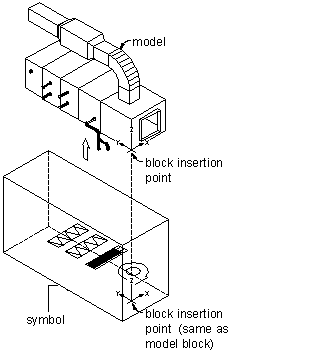
- Under Base Point, click the Pick Point option and select the block insertion point.
The insertion point, or base point, is used as a reference for positioning the block.
- Under Description, enter text to help identify the symbol block for easy retrieval.
- To attach a hyperlink to the part, click Hyperlink, select a file or web page, and click OK twice.
The symbol block is saved in the current drawing.