- Add duct and lay out the duct run, as explained in Drawing a Duct Run.
- In the Properties palette
 Advanced Labels and Flow Arrows, specify a selection for style.
 - Under Layout Method, specify how many labels or flow arrows to add to each duct segment you select, as follows:
To... then... Specify the total number of labels or flow arrows to display on each duct segment select By quantity, and enter a value for Number of labels. Note that the number of labels or flow arrows is automatically added to each straight segment. Insert a label or flow arrow at a uniform interval on each duct segment select By distance, and enter a value for Distance between. Note that if a duct segment length is less than the interval distance, a label or flow arrow is not added to that segment. 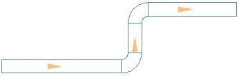
Flow Arrows Spaced Evenly, 1 per segment
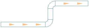
Flow Arrows Repeated at a Uniform Interval
- To disable Labels and Flow Arrows select NONE for style.
- If you specified One by one for the layout method, specify the location on the duct to add the label.
By default, the label is placed along the duct segment. Press Ctrl before specifying the label location to move the label off the duct.
Remember: Label styles can be configured to display properties such as duct diameter or system type.