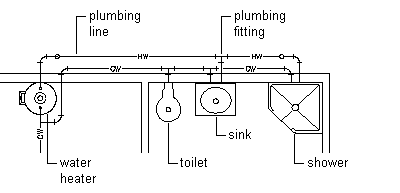
After you place the equipment and fixtures in the drawing, you can create a plumbing run. A plumbing run is a set of plumbing lines, consisting of individually drawn segments, that carry gas or fluid from one point to another. A network is the set of interconnected plumbing runs within a system, such as those that carry waste water from the connected toilets, sinks, and showers to the main drain line.

Domestic hot and cold water system
Before you draw a plumbing run, you specify a system for the segment on the plumbing line Properties palette. As you draw the run, the software inserts plumbing fittings based on the default fittings configured for that system definition. However, when necessary, you can override the default fittings for an individual run or manually add an individual fitting. For information on specifying default fittings, see Specifying the Default Fittings for a Plumbing System Definition.
Plumbing lines are 2-dimensional (2D) and can be system-based and style-based. For this reason, before you add plumbing lines to a drawing, you should define the plumbing systems, plumbing line styles, and plumbing fitting styles.
The plumbing line system determines the system type (i.e., Cold Water, Waste, or Fire Protection), the fittings that the software inserts when necessary, and other properties. Systems help maintain consistency throughout a run and across multiple drawings in a project. Once you define the plumbing systems, you select a system on the Properties palette as you draw plumbing runs. For more information, see Configuring Plumbing System Definitions.
The plumbing line style determines the appearance and function, such as the available standard sizes and how crossing plumbing lines display in plan view. You can create plumbing line styles based on information such as the size, type, and gauge of the material (i.e., Schedule 40 Carbon Steel or Copper Tube). As with systems, once you define the styles, you can select a style on the Properties palette as you draw plumbing runs.