The graphical 1-line display shows a generalized routing of a duct system, using non-scaled components. It displays equipment as schematic symbols but does not show a fitting or joint type. The sizes of components and equipment symbols are related to the physical model location but not to their actual dimensions.
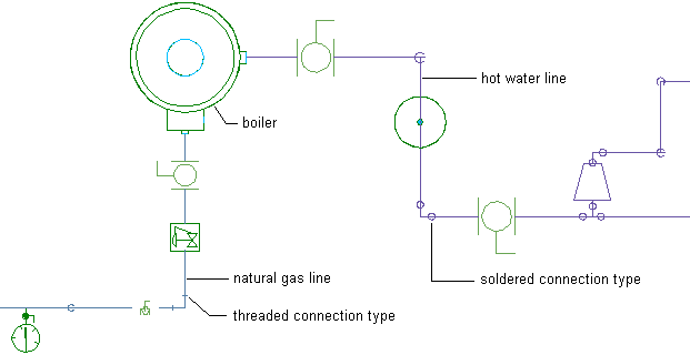
The following example shows a natural gas line and hot water line connected to a boiler. The ducts and their in-line components, including valves, reducers, a pressure regulator, and a pressure gauge, display as 1-line symbols. The boiler displays as a scaled 2-line component. The gas line uses threaded connections, while the hot water line uses soldered connections. The connection types are indicated on the fittings.
Using a 1-line or 2-line display to plot a large duct system, the fittings and equipment on smaller duct runs might not render well because they are so small compared to the size of the entire system. If you use the graphical 1-line display for smaller diameter duct systems, the fittings and equipment symbols plot at a specified size.
Graphical 1-line does not alter the components in the system. Duct components still contain the defined properties, such as size, type, and system, and can be changed to display as scaled 1-line or 2-line.