When you draw a wire, you can select a style for the wire on the Properties palette. The style determines the annotation properties for the wire, such as the tick marks to use for conductor, neutral, and ground wiring; the symbol to use for home run arrows; and how to display connections.
The style of a wire also determines how crossing wires are displayed. You can display crossing wires as is, or with an overlap or a break of a specific width.
In a drawing, the order in which the wires were drawn determines which wire displays the overlap or break.

To specify annotation for a wire style
- Open the style by doing one of the following:
- From the Electrical workspace, click
.
 In the left pane of the Style Manager, expand Electrical Objects, then expand Wire Styles, and select the style.
 - In the drawing, select a wire that uses the style and click
.

- From the Electrical workspace, click
- Click the Annotation tab.
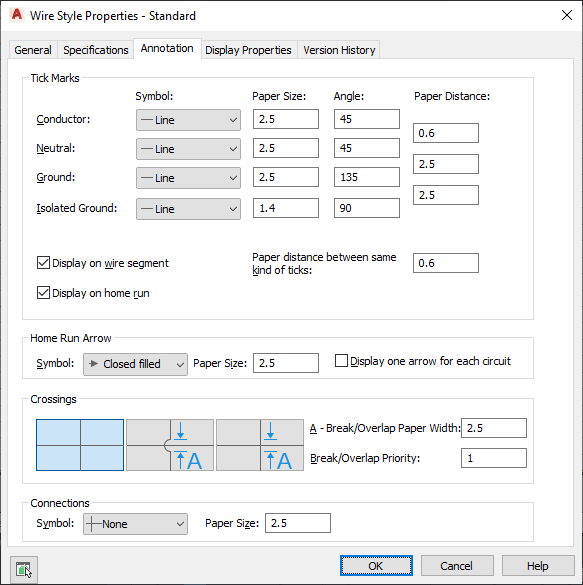
- Under Tick Marks, select a symbol type, and enter a tick mark size and angle for conductor, neutral, and ground.
- For Distance, enter the spacing for tick marks between conductor and neutral wires, or neutral and ground wires.
- Specify how to display tick marks:
- To show tick marks on each segment, select Display on wire segment.
- To show tick marks on home runs, select Display on home run.
- For Paper distance between same kind of ticks, enter the distance between the tick marks on a segment.
- Under Home Run Arrow, select an arrow style, and enter a size.
To show only one home run arrow for each circuit, select Display one arrow for each circuit.
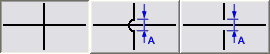
- Under Crossings, select a style for crossing wires.
You can specify that the crossing wires are displayed as is, with an overlap, or with a break.
- If you selected the overlap style or the break style, for Break/Overlap Paper Width, enter the width of the overlap or the break, and for Break/Overlap Priority, enter a number.
- Under Connections, select a connection node symbol type for wire junctions, and enter a size.