Schematic symbols are connected to lines with anchors.
To add schematic symbols in isometric mode
- In the Schematic workspace, start the add command by doing one of the following:
- Open a schematic tool palette, and select a schematic symbol tool.
If necessary, scroll to display the tool. Because tools contain preconfigured properties for the objects they create, you might not need or be able to specify some of the schematic symbol properties referenced in this procedure.
- Select a schematic line and click

 .
.
- Click
.
- Enter symboladd.
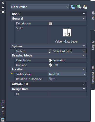
Note: On the Properties palette, indicates a property is available only when you are adding schematic symbols, not when you are modifying them.
- Open a schematic tool palette, and select a schematic symbol tool.
- On the Properties palette, if necessary, specify or change the symbol to add by selecting a schematic symbol style:
If you want to select a schematic symbol style… then… in the current drawing in the Properties palette Basic General Style click the image. In the Styles Browser palette that displays, set the Drawing Source to Content Library Drawings File to Current Drawing.
in a drawing in the directory specified as the default content location for schematic symbols in the Properties palette Basic General Style click the image. In the Styles Browser palette that displays, set the Drawing File to Current Drawing.
Note: Not all schematic symbols provided with the software have isometric views. Drawings containing symbols with both orthographic and isometric views are named accordingly.in the style drawing referenced in the properties of a tool you selected in the Properties palette Basic General Style click the image. In the Styles Browser palette that displays, set the Drawing Source to Currently Open Drawings, and Drawing File to All Drawings.
- For Description, click
 , enter a description for the schematic symbol, and click OK.
- For System, select the system to which the schematic symbol belongs.
- For Orientation, select Isometric, and for Isoplane, select the isoplane onto which to place the symbol.
Note: If the style you selected does not have any defined isometric views, Orientation is read-only and set to Ortho. If this is the case, select a different style.
- For Justification, select the point on the symbol to use as the insertion point.
You can select either the insertion point of the view block that represents the symbol, or one of 9 other points on the device, such as Top Left or Middle Center.
- Expand Advanced, and for ID, enter the ID to use to identify this symbol.
You can add the ID to your diagram as a label. The label style that you select when you add the label determines the font and size of the ID.
- In the drawing, click to specify the insertion point, which typically is a point on a schematic line.
If you specify a point on a line, the symbol breaks into and aligns with the line. It then behaves like an in-line symbol.
Tip: Use object snaps, such as Nearest or Midpoint, to help place schematic symbols. - Rotate the symbol into position by doing one of the following:
- In the drawing, use the compass to rotate the symbol.
- On the command line, enter the angle of rotation, and press ENTER.
- Enter is (iso rotation), enter the orientation of the symbol within the isoplane (right, up, left, or down), and press Enter.
Alternatively, you can press Enter to accept the default rotation.
Note: The rotation is applied only to end-of-line symbols. The rotation of an in-line symbol is determined by the line into which it is inserted. - Repeat the previous 2 steps to insert additional symbols with the same properties.
- To change isoplanes as you draw, on the Properties palette, select a different isoplane for Isoplane, and then continue to add symbols.
The UCS icon and crosshairs adjust to the selected isoplane.
- If necessary, on the Properties palette, modify the schematic symbol properties, and add additional symbols.
- Press Enter to end the add command.
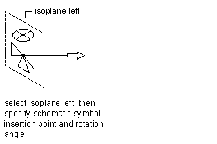
Adding a schematic symbol to the left isoplane
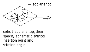
Adding a schematic symbol to the top isoplane
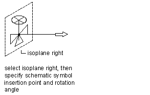
Adding a schematic symbol to the right isoplane