Use this procedure to route parallel runs in piping systems.
To connect the baseline pipe to a radiator valve
- If necessary, activate the Piping workspace.
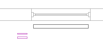
- Create 2 or more starting parallel pipe segments. For each segment, specify properties, such as the routing preference and the system.
- Click
 .
.
 Tip: You can also start the command by entering PARALLELROUTING on the command line.
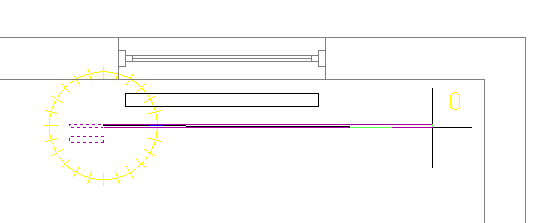
 - Select a baseline pipe.
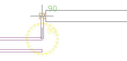
Routing begins at the open end of the baseline pipe. If the pipe is open at both ends, select the pipe by clicking near the end where you want the routing to begin.
- Select one or more pipes to be routed parallel to the baseline pipe, and press Enter.
The baseline pipe becomes active.
- Add pipe segments.
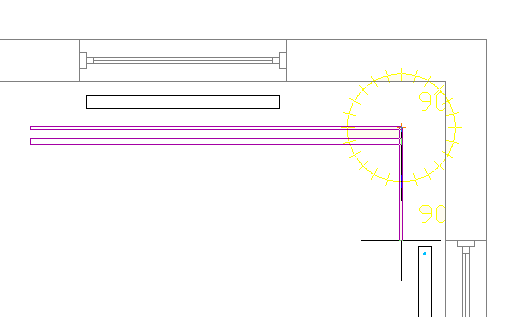
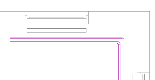
The software adds pipe segments to the baseline pipe and the parallel pipe(s). Each pipe segment is created according to the routing preferences and properties specified for the starting pipe segment. A constant distance is maintained between the pipe segments where possible.
 Note: If the routing preference for one or more of the pipes does not specify a required pipe type or fitting, the Choose a Part dialog box prompts you to specify a different part. See Choosing a Part for more information.
 -
If you make changes on the Properties palette, the following guidelines apply:
- A change to a property that guides the placement of the baseline pipe, such as Justification or Compass, applies only to the baseline pipe.
- A change that affects the physical characteristics of a pipe segment being created, such as Size or Insulation Thickness, affects all pipe segments in the run.
- A new Elevation value modifies the elevation of all pipes being routed. The distance between the pipes is maintained over the elevation change unless it results in a conflict.
- You cannot change some properties, including System, Routing Preferences, Fitting Settings, and Layout Method, while the PARALLELROUTING command is active.
- To designate a different pipe as the baseline pipe, enter
b.
The current routing options, such as Justification or Compass, apply to the new baseline pipe.
- Click the Pipe End Connector on the valve.
- Enter
a to accept the displayed solution.
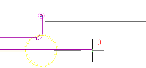
Another pipe becomes the baseline pipe. When only one pipe remains to be routed, the PARALLELROUTING tool behaves like PIPEADD.
- End the command by doing one of the following:
- Connect the final pipe to an object, such as a radiator valve or another pipe.
- Press Enter.