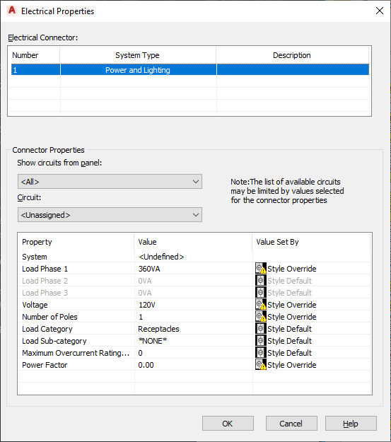
You modify the electrical connectors of a device using the Electrical Properties worksheet.

When modifying a connector, keep in mind the following:
- If a circuit is specified for the connector, the System value is not editable. If the system type of the connector is Power and Lighting, then the values for Voltage and for Number of poles are also uneditable. This prevents changes that do not agree with the selected circuit. You can make these properties editable by selecting Unassigned for Circuit.
- If a circuit is not specified for the connector, and a property is still not editable, this is because the device style does not allow the override of the value specified in the style. For information about allowing and preventing style overrides, see Configuring Connectors for Device Styles and Panel Styles.
- When you assign or change the circuit of a connector, or when you modify the load or load category of the connector, the affected circuits are updated accordingly and evaluated for overloads. In the circuiting preferences, you can specify whether the software warns you of the overloads, so you can decide whether to proceed or cancel the action. If you overload a circuit, you are not notified of the overload again within the drawing session.
When modifying the connectors on multiple selected devices, also keep in the mind the following:
- If you overload a circuit when you are modifying devices assigned to different circuits, you are still notified of the overload as described above. However, you must use the Circuit Manager to identify the overloaded circuit.
- If a property is not editable for at least one of the selected devices, it is read-only.
- The electrical connectors on all the selected devices are listed by number. If a connector of a given number has a different system type for at least one of the devices, *VARIES* is shown for System Type, and only the properties in common are shown.
- *VARIES* is also shown for any other property that does not have the same value for all of the selected devices.
- Power and Lighting connectors only: *VARIES* is also shown for properties with values that are retrieved from different sources (for example, style override versus By Circuit). Additionally, when the value is By Circuit for all of the selected devices, *VARIES* is shown if the selected connector on all of the devices is not assigned to the same circuit. Refer to the following table for example scenarios.
Value for connector 1 on device 1 Value for connector 1 on device 2 Value displayed in worksheet value is the style default <By Circuit> [same value as for device 1] *VARIES* value is a style override <By Circuit> [same value as for device 1] *VARIES* <By Circuit> <By Circuit> <By Circuit> <By Circuit> [value from assigned circuit] <By Circuit> <By Circuit> [*VARIES*] <By Circuit> [value from circuit 1] <By Circuit> [value from circuit 1] <By Circuit> [value from circuit 1] <By Circuit> [value from circuit 1] <By Circuit> [value from circuit 2] <By Circuit> [*VARIES*]
To modify the electrical connectors of devices
Optionally assign the connector to a circuit
Specify the connector properties
- Select the devices, and click

 .
.
- On the Electrical Properties worksheet, select a connector.
- If necessary, you can filter the list of available circuits by selecting a panel for Show circuits from panel, and by specifying values for the connector properties.
The selections available for Circuit include the circuits in the current drawing, and, if specified for the current drawing, in the electrical project database that match the values you have specified for the connector properties, and that have a system type of General. If the system type of the selected connector on all of the devices is the same, the selections also include the circuits that have that system type (Power and Lighting, or Other). However, if the system type of the connector varies across the selected devices, the selections are limited according to their values.
Beside each circuit name, the current load on the circuit is displayed. The load is the total load on the circuit across all applicable drawings, including the electrical project database.
- For Circuit, do one of the following:
- Select a circuit to assign the selected connector on all of the devices to it.
- Select Unassigned to remove any circuit assignments from the devices.
Note: Once a circuit is selected, the System value is not editable. If the system type of the connector is Power and Lighting, then the values for Voltage and for Number of poles are also uneditable. This prevents changes that do not agree with the selected circuit. - Under Value, specify values for the connector properties.
For descriptions of each property, see Configuring the Electrical Connectors of a Device.
If you are using the electrical project database, and have more than one drawing open, you can reload the electrical project database in each open drawing. This updates the circuit information for each drawing. For example, if you modify a device load, or change the circuit assignment for the device, you can reload the electrical project database in other open drawings to reflect these changes.