When you are drawing in orthographic mode, you add schematic symbols in the world coordinate system (WCS). In the WCS, the X axis is horizontal, the Y axis is vertical, and the Z axis is perpendicular to the XY plane.
You can use the compass to guide your placement of symbols. You can also use the AutoCAD® Ortho mode to restrict the cursor movement to the horizontal or vertical axes. The orthogonal alignment depends on the current grid and snap settings. You can turn these tools on or off at any time.
Schematic symbols are connected to lines with anchors.
- In the Schematic workspace, start the add command by doing one of the following:
- Open a schematic tool palette, and select a schematic symbol tool.
If necessary, scroll to display the tool. Because tools contain pre-configured properties for the objects they create, you might not need or be able to specify some of the schematic symbol properties referenced in this procedure.
- Select a schematic line, and click

 .
.
- Click
.
- Enter symboladd.
Note: On the Properties palette, indicates a property is available only when you are adding schematic symbols, not when you are modifying them.
- Open a schematic tool palette, and select a schematic symbol tool.
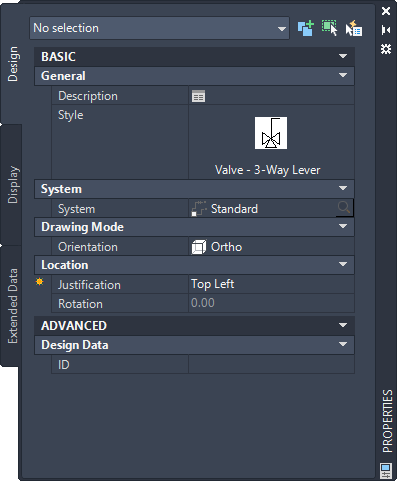
- On the Properties palette, if necessary, specify or change the symbol to add by selecting a schematic symbol style:
If you want to select a schematic symbol style… then… in the current drawing in the Properties palette Basic General Style click the image. In the Styles Browser palette that displays, set the Drawing Source to Content Library Drawings File to Current Drawing.
in a drawing in the directory specified as the default content location for schematic symbols in the Properties palette Basic General Style click the image. In the Styles Browser palette that displays, set the Drawing File to Current Drawing.
Note: Not all schematic symbols provided with the software have isometric views. Drawings containing symbols with both orthographic and isometric views are named accordingly.in the style drawing referenced in the properties of a tool you selected in the Properties palette Basic General Style click the image. In the Styles Browser palette that displays, set the Drawing Source to Currently Open Drawings, and Drawing File to All Drawings.
- For Description, click
 , enter a description for the schematic symbol, and click OK.
- For System, select the system to which the schematic symbol belongs.
You can select from the systems in the current drawing.
- If Orientation is enabled under Drawing Mode, select Ortho.
Note: If the style you selected does not have any defined isometric views, Orientation is read-only and set to Ortho.
- For Justification, select the point on the symbol to use as the insertion point.
You can select either the insertion point of the view block that represents the symbol, or one of 9 other points on the device, such as Top Left or Middle Center.
- Expand Advanced, and for ID, enter the ID to use to identify this symbol.
You can add the ID to your diagram as a label. The label style that you select when you add the label determines the font and size of the ID.
- In the drawing, click to specify the insertion point.
If you specify a point on a schematic line, the symbol breaks into and aligns with the line. It then behaves like an in-line symbol.
Tip: Use object snaps, such as Nearest or Midpoint, to help place schematic symbols. - Rotate the symbol into position, or enter the angle of rotation on the command line.
Alternatively, to accept the default rotation, press Enter.
Note: The rotation is applied only to end-of-line symbols. The rotation of an in-line symbol is determined by the schematic line into which it is inserted. - Repeat the previous 2 steps to insert additional symbols with the same properties.
You can also modify the properties on the palette, and then add additional symbols.
- Press Enter to end the add command.