In some regions, construction documents must show building system objects differently based on their elevation. For example, you might be required to display an object below the floor slab in the plan view with one linetype, and another object above the floor slab but below the cut plane with another linetype.

You can meet such requirements using the Display by Elevation feature. The Display by Elevation feature includes the following elevation-based display components:
- Contour
- Connector
- Center Line
- Hatch
- Insulation
- Lining
- Rise Drop
- Annotation
You can configure these display components to show or hide the following AutoCAD MEP 2023 toolset objects relative to the floor plan and the cut plane:
- Cable tray, cable tray fitting
- Conduit, conduit fitting
- Duct, flexible duct, duct fittings, and custom duct fitting
- MvParts
- Pipe, flexible pipe, pipe fitting, custom pipe fitting
Any rise/drop symbols associated with these objects will inherit the elevation-based display characteristics of the parent object.
If you create a 2D section or 2D elevation with a display set that uses 1-Line or Plan display representations, the section or elevation also shows the objects with the elevation-based display properties.
The elevation-based display components control the display of objects when the following conditions are met:
- The Display by Elevation feature is enabled.
- The current view is Top (plan).
- The current display configuration uses 1-Line or Plan display representations.
You can configure elevation-based display components using the Style Manager or the Display Manager. The following example shows contour display components in the Display Manager when the Display by Elevation feature is enabled:
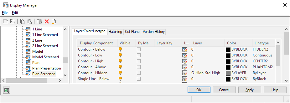
Display settings differentiate objects above or below the display range. For example, you can set linetypes and line colors to display differently depending on elevation. You can also use the display settings to hide an object based on its elevation. Hiding objects is useful when you create construction documents for a specific floor plan from a model that spans multiple stories.
You can also configure elevation-based display components that apply to a particular object in the drawing using the Display tab of the Properties palette.
The next example shows the Display tab with the relevant display component based on the elevation of the selected object. The cut height is 2500 mm, the display above range is 3500 mm, and the display below range is 0. At an elevation of -1000 mm, the duct object, located below the display range, is hidden.

Duct object located below display range