In the block-based building environment, you can add connectors to the part. Connectors enable the part to be connected intelligently to other building systems objects in your layout. You can define one or more connectors for the part.
When you add a connector, you specify a domain. The domain is a predefined list that specifies the connection rules for a part. The domain is defined once for the part family and remains the same for all part sizes. Connectors belonging to a particular domain can connect to other parts of the same domain, but they cannot connect to components in other domains. For example, an MvPart representing an air handling unit might have the following domains specified for its connections:
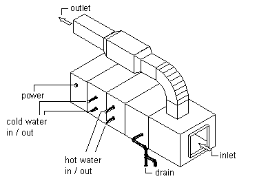
| Connector Name | Description | Domain |
|---|---|---|
| inlet | air entering the unit | duct |
| outlet | air leaving the unit | duct |
| power | electrical connection to the motor | conduit |
| hot water in | hot water entering the heating coil | pipe |
| hot water out | hot water leaving the heating coil | pipe |
| cold water in | cold water entering the chilling coil | pipe |
| cold water out | cold water leaving the chilling coil | pipe |
| drain | condensation drain | pipe |
The connector shape is dependent on the specified shape of the part family; however, you can specify the type, size, and location for each connector based on the part size. The connector type is specified from a list of predefined types by domain and defines additional connection rules for a part. Examples of connector types include flange, slip-joint, and glued. The size is a user-defined value and varies by shape. For example, for a rectangular shape you can define the length and width, whereas for a round shape you can define the diameter. However, you can specify whether unsized connections are allowed when defining each connector.
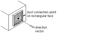
The location of a connector can be specified by entering coordinates based on the 3D model of the part or by picking an insertion point. You must also specify a direction vector, or normal, that sets the direction of the connector when leaving the part, typically pointing in the direction away from the part size. If you assign the direction vector correctly, the Compass is aligned when you connect components to the part.
Recommended direction vectors are as follows:
- positive x direction: 1,0,0
- positive y direction: 0,1,0
- positive z direction: 0,0,1
- negative x direction: -1,0,0
- negative y direction: 0,-1,0
- negative z direction: 0,0,-1
For connector faces that are rotated on non-standard planes, specify the connection position using drawing assistance to snap to the center of the connector face, and specify the direction pointing away from the part. You can also specify a rotation; however, the rotation typically is specified by default upon insertion.