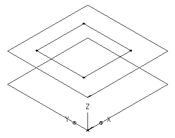
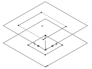
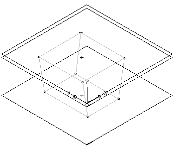
Use this procedure to model a parametric air terminal MvPart. You add the rectangular geometry for the top and bottom faces, create the profiles, add constraints to align the faces, and apply the modifiers to create the transition between faces.
To create the face geometry
- To create the top face of the diffuser, in the part browser, right-click XY Plane and click Add Profile
 Rectangular.
 For more information about profiles, see Profiles.
- Specify the first corner in the modeling area and then the second corner.

A rectangular profile for the top face is created and is added to the XY plane in the part browser. Constraints for the rectangular profile are also added to the XY plane.
- To add an offset work plane to help locate the bottom face of the diffuser, in the part browser, right-click Work Planes and click Add Work Plane.
The Create Work Plane dialog box is displayed.
- Click Offset and enter Bottom Face for Name. Click OK.
- In the modeling area, select the XY plane as the reference work plane, drag the cursor below the XY plane, and enter 12" (305 mm) for the offset distance.
The bottom face work plane is created.

- To create the bottom face of the diffuser, in the part browser, right-click Bottom Face and click Add Profile
 Rectangular.
 - Specify the first corner in the modeling area and then the second corner.

A rectangular profile is created for the bottom face and is added to Bottom Face in the part browser. Constraints for the rectangular profile are also added to Bottom Face.
To add constraints to align the faces
- In the part browser, right-click XY Plane and click Add Geometry
 Point.
 - In the modeling area, specify a point near the center of the top face rectangular profile and press Enter.
- In the part browser, right-click XY Plane and click Add Constraints
 Equal Distance.
 - In the modeling area, specify the pairs of geometric constraints.
For the first pair, select the point in the center of the top face, and then the lower-left edge of the top face rectangular profile.
For the second pair, select the point in the center of the top face, and then the upper-right edge of the top face rectangular profile.
The model of the top face is updated to the specified constraint.

- Repeat steps 3 and 4 to constrain the upper-left and lower-right edges of the top face.
The model of the top face is updated to the specified constraint.
 Note: When adding constraints, you may be prompted that the geometry is unconstrained by a specific number of dimensions. These prompts are for informational purposes only to assist you during the modeling process. It is recommended that you add a minimum number of constraints to define the shape of the part to avoid undesirable results.
 - To ensure the alignment of the top and bottom faces, in the part browser, right-click Bottom Face and click Add Geometry
 Point Reference.
 - Select the existing point in the center of the top face rectangular profile.
A reference point is added to the bottom face work plane.

- Repeat steps 3 through 5 to constrain all 4 edges of the bottom face using the reference point in the center of the bottom face.
The model of the bottom face is updated to the specified constraints.

To apply the modifiers
- In the part browser, right-click Modifiers and click Add Transition.
For more information about modifiers, see Modifiers.
- In the modeling area, select the top face rectangular profile for the start profile; then select the bottom face rectangular profile for the end profile.
A transitional box is created to represent the diffuser, and a transition modifier is added to Modifiers in the part browser.

- To add the lip of the diffuser, in the part browser, right-click Work Planes and click Add Work Plane.
The Create Work Plane dialog box is displayed.
- Click Offset and enter Lip Offset for Name. Click OK.
- In the modeling area, select the XY plane as the reference work plane, drag the cursor above the XY plane, and enter 1" (25 mm) for the offset distance.
The Lip Offset work plane is created.

- In the part browser, expand Modifiers, right-click Transition Modifier, and click Visible.
The transition modifier display is turned off in the modeling area.
- In the part browser, right-click Modifiers, click Add Extrusion, and select the top face rectangular profile.
The Extrusion Modifier dialog box is displayed.
- Under Termination, select Plane for Type, and select Lip Offset for To. Click OK.

A box is created to represent the top lip of the diffuser, and an extrusion modifier is added to Modifiers in the part browser.
- To see the entire model of the part, in the part browser, right-click Transition Modifier and click Visible.
