AutoCAD Mechanical toolset provides a way to differentiate between selecting model space geometry (that belongs to a component view/folder) and selecting a component view/folder.
At the time you click the geometry to select it, observe the tooltip. The tooltip indicates what is being selected. If it is the geometry that is selected, the name of the geometry is shown. If it is the component view/folder that is selected, the name of the component view is shown. Continue clicking the geometry until the tooltip shows the name of the entity you want to select.
The status bar contains three buttons that control how structure objects are selected in model space.
- Structure selection order status bar button (Selection mode is top-down = Find. Selection mode is bottom-up = Find.)
When the selection order is set to bottom up, the first click selects the geometry, the next click selects the part, the next click selects the subassembly, and the next click selects the next higher level assembly, and so on until the top-level assembly is selected. A tooltip (not shown in the image) displays the name of the object selected, as you click.
 Note: No grip point is shown when the entire assembly is selected. This is because the number of entities selected exceeds the Object selection limit for display of grips setting in the Selection tab of the Options dialog box (OPTIONS command).
When the selection order is set to top down, the first click selects the top-level assembly, the next click selects the next level of a subassembly, and so on until the geometry is selected. A tooltip (not shown in the image) displays the name of the object selected, as you click.

- Reference lock status bar button (Reference lock is on =
 . Reference lock is off= Find)
 When no component views or folders are activated, the reference lock prevents you from grip editing component view or folder geometry of external reference (xref) components or folders. This acts as a protection from inadvertently changing xref geometry, which may be referred to in other drawings.
- Selection lock status bar button (Selection lock is on=
 . Selection lock is off= Find.)
 When a component view or folder is activated, the selection lock prevents you from selecting geometry that does not belong to the activated component view or folder.
Window selection and the structure selection order
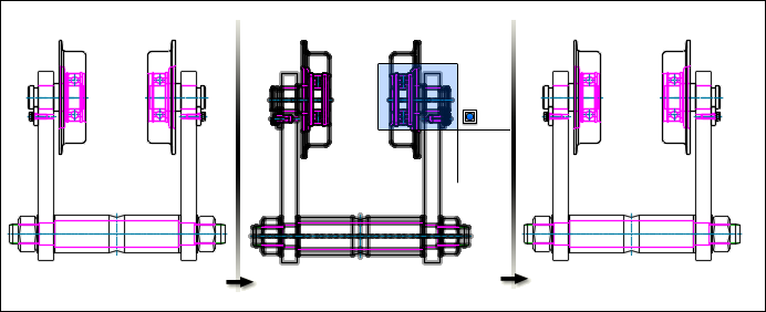
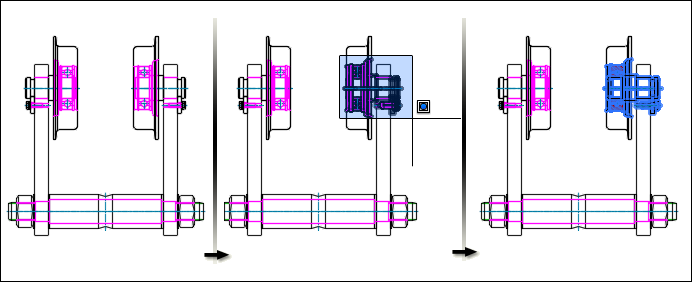
Window selection refers to the selection of objects by enclosing them in a rectangular area created by dragging the cursor from left to right. When the structure selection mode is set to top down, window selection does not select any objects.

When the selection mode is set to bottom up, window selection selects the components (not the geometry) that are enclosed.

Crossing selection and the structure selection order
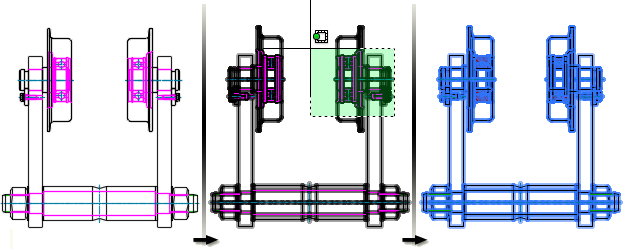
Crossing selection refers to the selection of objects by enclosing or crossing them in a rectangular area created by dragging the cursor from right to left. When the structure selection mode is set to top down, crossing selection selects the top most assembly of the objects it crosses.

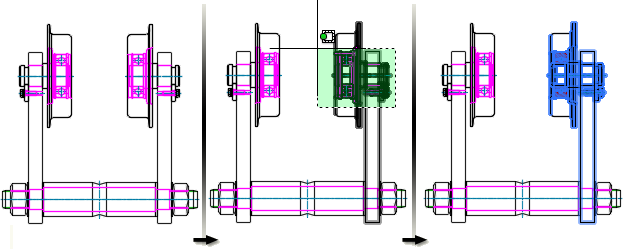
When the selection mode is set to bottom up, crossing selection selects only the components (not the geometry) that are enclosed/crossed.
