In this exercise, you use the contour follower to vectorize raster contours and record their elevation.
| To convert a raster contour to a vector polyline | ||
|---|---|---|
| 1 |
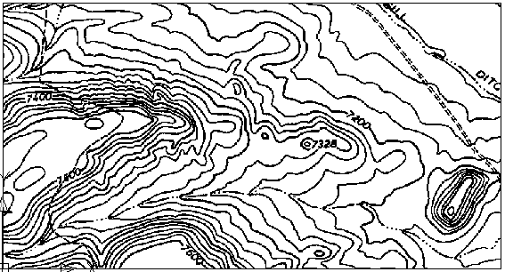
Open the LiveView_Contour.dwg sample file. You see a small contour map of rugged terrain. |
 |
| 2 |
On the ribbon, click
Raster Tools tab Click the VTools Follower tab. In the Contour Settings area, select Contour Creates Polyline and set Elevation Interval to 20. Click OK. These settings ensure that when you trace a raster contour, it is replaced by a vector polyline and the original raster is erased. |
  |
| 3 |
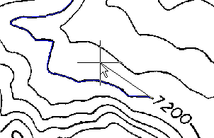
Zoom your display in to see the 7200 contour. On the ribbon, click
Raster Tools tab |
 |
| 4 |
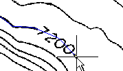
Click one or two points across the label gap. Enter o to continue the line to the end. Right-click and click Enter. Enter 7200 for the elevation. |
 |
| 5 |
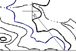
Click the contour line to the left of 7200, then right-click and choose Enter. Because it has no label gap, this line is vectorized completely with one click.On the command line, you are prompted with 7220, the correct elevation for this line. This occurs because you set AutoCAD Raster Design toolset options to match the elevation interval in the drawing. Press Enter to accept the elevation, then press Esc to end the command. |
 |
