In this exercise, you see how different band assignment color maps assist the visual analysis of a multispectral data set.
| To edit a band assignment color map | ||
|---|---|---|
| 1 |
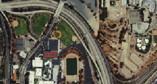
Open the LiveView_ColorMap2.dwg sample file. A satellite image is displayed that shows some urban terrain in normal colors. |
 |
| 2 |
If the
Image Manager toolspace is not open, on the ribbon, click
Raster Tools tab |
 |
| 3 |
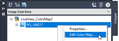
In the Image Insertions view, expand the LiveView_ColorMap2 node, right-click the image name and choose Edit Color Map. |
 |
| 4 |
In the Band Assignment Color Map dialog box, note that the red, green, and blue channels on the left are assigned to the corresponding red, green, and blue data bands. |
 |
| 5 |
In the Band Assignment Color Map dialog box, use the three drop-down lists to assign the color channels as follows:
Click Apply to see the change immediately, and click OK to close the dialog box. |
 |
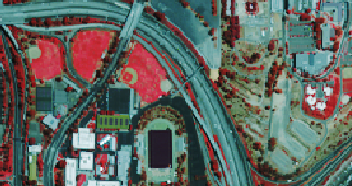
| 6 | This color map shows vegetation as red. Vegetation that is healthy or more dense appears darker red. This type of display is known as a false color image, and this particular band assignment is commonly used for analyzing vegetation. |
 |
