The following exercise is presented to demonstrate the best way to insert and then annotate parcel data. There are three parts to the operation:
- Insert an xref of the parcel drawing into a drawing that contains AutoCAD objects.
- Label the lot lines.
- Edit the resulting labels.
Open source.dwg and current.dwg in C:\Program Files\AutoCAD 2023\C3D\Help\Civil Best Practices Guide.
- Maximize
current.dwg, and click Insert Tab
 Reference panel
  Attach
 . In the Select Reference File dialog box, navigate to
source.dwg, select it and click Open.
- In the
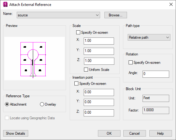
External Reference dialog box, set Insertion Point to 0,0,0, Scale to 1,1,1, and Rotation Angle to 0.
It is recommended that you set the Path Type to Relative Path.

Figure 15: Required settings for Xref labeling
- Click OK.
- Add labels as you would for regular data. Click


 . Label all of the lines and curves that comprise LOT7 and LOT16, which are xref data. The labeling commands work as they do for regular objects.
- Select and right-click the xref parcels and observe the xref commands that are available.
Note:
The xref data is highlighted with dashed lines when selected. The xref commands affect the corresponding labels in various ways. If you detach or bind the xref, the label is deleted and must be recreated.
- Right-click a parcel that exists in the current drawing and note the context menu.
Note:
When you label xrefs, designate them as such to avoid confusion. With the Text Component Editor, add a convention to the label text for identification. This is an easy way to differentiate xref and native object data.