Subassembly Composer
The Autodesk® Subassembly Composer for Autodesk® Civil 3D® 2023 provides an interface for composing and modifying complex subassemblies, without a need for programming.
What is it?
Autodesk Subassembly Composer for Civil 3D provides you with an interface for composing and modifying complex subassemblies with no programming knowledge required. It is available to be installed when installing AutoCAD Civil 3D. Customizing subassemblies allows you to create subassemblies that meet your specific needs. Once a subassembly is imported to Civil 3D, you can use them whenever you want.

Why use it?
Working with existing built-in assemblies and subassemblies in civil 3D can be challenging. Using the subassembly composer allows you to quickly develop your own subassemblies that meet your specific requirements and can be saved and reused for later projects. Because the default subassemblies available in the Civil 3D Tool Palette are not always a perfect fit for a project we can use the subassembly composer to develop subassemblies that fit our requirements.
Subassembly developers can compose complex subassemblies visually, using a powerful yet easy-to-use interface:
- Define the behavior of a subassembly using an easy to understand flowchart.
- Drag and drop common geometry elements and conditions from the categorized a tool box onto the flowchart.
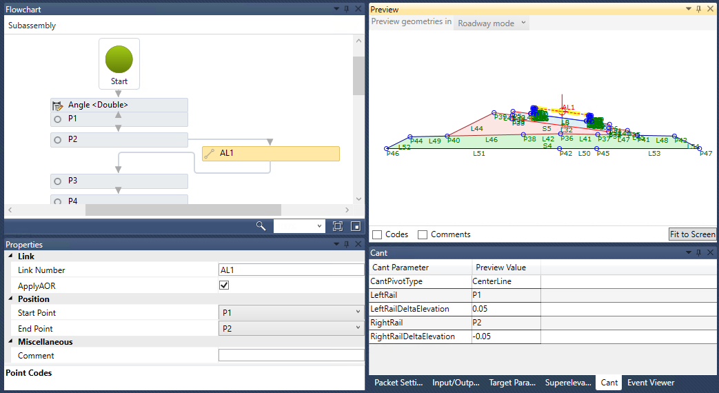
- See a preview of the subassembly geometry, and simulate how the subassembly behaves with different target values and conditions.
- Find and edit the properties of a subassembly element using the synchronized flowchart and preview.
- Attach help documentation to the subassembly.
- Save subassemblies as PKT files. The PKT files can be imported into Autodesk Civil 3D, which automatically generates ATC files.
The Autodesk Subassembly Composer for Autodesk Civil 3D provides a strong set of subassembly functionality for corridor modeling:
- Define points using several methods.
- Define links between points.
- Define shapes surrounded by links.
- Define advanced geometry elements, such as curves, fillets, and intersection points.
- Get and set marked points.
- Define auxiliary geometry elements as a basis for other subassembly geometry elements.
- Assign point, link, and shape codes.
- Define targets and input/output parameters.
- Organize geometry elements, or add conditional behavior.
- Define and set variables.
- Define complex logic with expressions and API functions.

How do I use it?
Creatinga Subassembly
- Create a project. Use the Civil 3D menu bar to create a subassembly project.
- Specify subassembly parameters in the settings and parameters panel.
- Drag and drop geometry elements from the Tool Box onto the Flowchart.
- Select each geometry element from the Flowchart, and modify its parameters in the Properties panel.
- Preview and verify the geometry in the Preview panel.
- Save the project the menu bar to save the subassembly.
Importing a Subassembly into Civil 3D
- Select each geometry element from the Flowchart, and verify the parameters in the Properties panel.
- Verify the geometry in the Preview panel.
- Review the settings and parameters panel to make sure the packet settings and parameters are correct.
- Use the menu bar to save the subassembly.
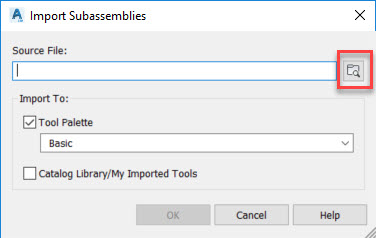
- Import the subassembly into Autodesk Civil 3D.
- Add the subassembly to an assembly, and then preview the corridor.

Editing a Subassembly
- Use the menu bar to open an existing PKT file.
- Specify subassembly parameters in the settings and parameters panel.
- Drag and drop geometry elements from the Tool Box onto the Flowchart.
- Select each geometry element from the Flowchart, and modify its parameters in the Properties panel.
- Verify the geometry in the Preview panel.
- Use the menu bar to save the subassembly.
Slanted Curb Subassembly
If you're working on a project that requires slanted curbs, you can open the Tool Palettes and realize that there is nothing there that looks like what you want, so you can’t use any of the existing subassemblies. You can solve this in Civil 3D if you create a closed polyline, turn it into a subassembly, then assign codes, links, and shape and it probably would be fine. The problem is that if you want to use different dimensions, you would have to create a new one. Instead of doing that, let’s create a parametric subassembly in Subassembly Composer.