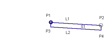
This subassembly is used to replace an existing sidewalk, starting at the existing outside edge of sidewalk and inserting surfaces towards the curb.
To use this subassembly, you should have separate alignments defining the existing outside edge of sidewalk information. Elevations at this point could come from a surface or a profile. Furthermore, if the component defining this edge is also another rehab component, then they could be passed in as marked points, thus transferring offset and elevation information.

Attachment
The attachment point is (near) the outside edge of the sidewalk. For better results, insert this on a controlling offset (with fixed offset) marker point during assembly construction.
Input Parameters
Note: All dimensions are in meters or feet unless otherwise noted. All slopes are in run-over-rise form (for example, 4 : 1) unless indicated as a percent slope with a “%” sign.
|
Parameter |
Description |
Type |
Default |
|---|---|---|---|
|
Side |
Specifies to insert the subassembly either on the right or the left side of the attachment point. |
Left/Right |
Right |
|
Outside Sidewalk Marked Point |
To define outside edge of sidewalk and elevation to start the subassembly (OPTIONAL) |
String |
None |
| Width | Width of the sidewalk, measuring inwards from high edge of sidewalk point |
Numeric |
1.5m 5.0ft |
| % Slope | Cross slope of sidewalk in %, measuring inwards from high edge of sidewalk |
Numeric |
-2% |
|
Depth |
Depth or thickness of the sidewalk |
Numeric, positive |
|
| Mark Inside Point | Name of the marked point to be stored at the new low edge of sidewalk (OPTIONAL) |
String |
None |
Target Parameters
This section lists the parameters in this subassembly that can be mapped to one or more target objects, such as a surface, alignment, or profile object in a drawing. For more information, see To Specify Corridor Targets.
|
Parameter |
Description |
Status |
|---|---|---|
| Outside Edge of Sidewalk | This will set the outside edge of proposed sidewalk as start point. The following object types can be used as targets for specifying this offset: alignments, polylines, features lines, or survey figures. |
Optional |
|
Left Gutter Profile |
This will set the outside edge elevation value of proposed sidewalk. The following object types can be used as targets for specifying this elevation: profiles, 3D polylines, feature lines, or survey figures. |
Optional |
| EGTopSurf | If profiles are not supplied for left/right edge of pavement elevations, then this surface elevation at that offset will be picked up as elevation value. The following object types can be used as targets for specifying this surfaces: surfaces. |
Required |
Output Parameters
|
Parameter |
Description |
Type |
Default |
|---|---|---|---|
| % Slope | Cross slope of sidewalk in %, measuring inwards from high edge of sidewalk |
Numeric |
-2% |
|
Depth |
Depth or thickness of the sidewalk |
Numeric, positive |
Behavior
By default outside edge of sidewalk is located at the attached marked point or at the associated alignment. Similarly, the elevation is set based on marker point associated, or profile, or from the surface at that offset.
Once this start point is established, sidewalk structure links are inserted inwards from this point for given width, slope, and depth. If a name is given for Mark Inside Point, a marked point is stored at the new low edge of sidewalk.
Layout Mode Operation
In layout mode, this subassembly starts at the attached point and draws a single shape with given dimensions, such as width, slope and depth.
While constructing an assembly, it is recommended that this subassembly be added at a controlling offset, if there is no previously marked point. This controlling offset could be at a decent offset from the baseline marker, so that the layout mode looks like a typical section. However, it is recommended that the user doesn't have to map this controlling offset to any "alignment/profile" in the corridor state, as that would cause problems such as making the design not perpendicular to the baseline in some cases. Not associating this controlling offset will not have any effect on the corridor, as the start point is attached to an alignment/marked point through the subassembly macro for an exact location.
Point, Link, and Shape Codes
|
Point / Link |
Code |
Description |
|---|---|---|
|
P1 |
Sidewalk_In |
Inside edge of sidewalk on finish grade |
|
P2 |
Sidewalk_Out |
Outside edge of sidewalk on finish grade |
|
L1 |
Top Sidewalk |
|
|
L2 |
Datum |
|
|
S1 |
Sidewalk |
Sidewalk concrete area |
Coding Diagram
