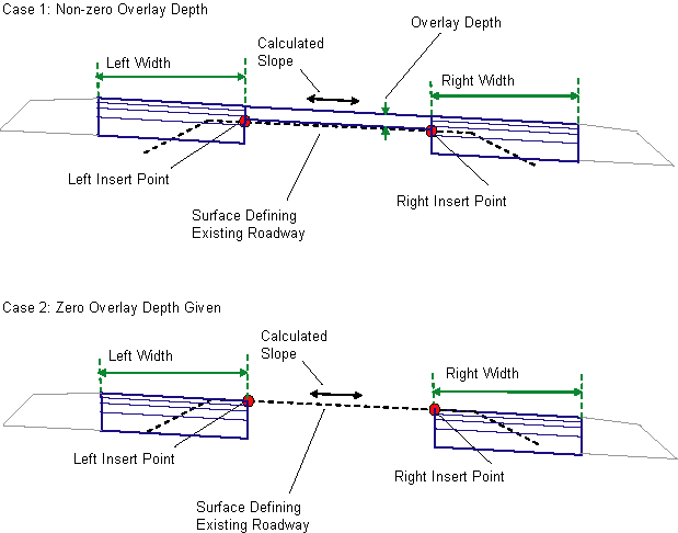
This subassembly overlays an existing uncrowned road, and adds one or more travel lanes to the left and right edges while matching the existing lane slope.

Attachment
The attachment point is at the inside edges of the finish grade on the widening lanes.
Input Parameters
Note: All dimensions are in meters or feet unless otherwise noted. All slopes are in run-over-rise form (for example, 4 : 1) unless indicated as a percent slope with a “%” sign.
|
Parameter |
Description |
Type |
Default |
|---|---|---|---|
|
Left Insert Point Offset |
Offset of the Left Insert Point. This is the point where the widening lane on the left begins, and is typically at the existing left edge-of-traveled-way. |
Numeric |
0.0 |
|
Right Insert Point Offset |
Offset of the Right Insert Point, typically at the existing right edge-of-traveled way |
Numeric |
0.0 |
|
Overlay Depth |
Depth of the overlay above the existing finish grade |
Numeric, positive |
0.100 m 0.30 ft |
|
Left Width |
Width of the left widening lane |
Numeric, positive |
3.6 m 12.0 ft |
|
Right Width |
Width of the right widening lane |
Numeric, positive |
3.6 m 12.0 ft |
|
Pave1 Depth |
Depth between finish grade and Pave1 |
Numeric, positive |
0.025m 0.083 ft |
|
Pave2 Depth |
Depth between Pave1 and Pave2 |
Numeric, positive |
0.025 m 0.083 ft |
|
Base Depth |
Depth between Pave2 and Base |
Numeric, positive |
0.100 m 0.333 ft |
|
Subbase Depth |
Depth between the subbase and the top of the base layer |
Numeric, positive |
0.300 m 1.0 ft |
Target Parameters
This section lists the parameters in this subassembly that can be mapped to one or more target objects, such as a surface, alignment, or profile object in a drawing. For more information, see To Specify Corridor Targets.
|
Parameter |
Description |
Status |
|---|---|---|
|
Existing Surface |
Name of the Surface defining the existing roadway. The following object types can be used as targets for specifying this surface: surfaces. |
Required |
|
Left Insert Point Offset |
May be used to override the fixed Left Insert Point Offset and tie the point to an offset alignment. The following object types can be used as targets for specifying this offset: alignments, polylines, feature lines, or survey figures. |
Optional |
|
Right Insert Point Offset |
May be used to override the fixed Right Insert Point Offset and tie the point to an offset alignment. The following object types can be used as targets for specifying this offset: alignments, polylines, feature lines, or survey figures. |
Optional |
|
Left Width |
May be used to override the fixed Left Width and tie the edge-of-lane to an offset alignment. The following object types can be used as targets for specifying this offset: alignments, polylines, feature lines, or survey figures. |
Optional |
|
Right Width |
May be used to override the fixed Right Width and tie the edge-of-lane to an offset alignment. The following object types can be used as targets for specifying this offset: alignments, polylines, feature lines, or survey figures. |
Optional |
Output Parameters
|
Parameter |
Description |
Type |
|---|---|---|
|
%Slope |
The calculated slope on the existing surface from the Sample Point to the Insert Point |
Numeric |
Behavior
The elevations of the Left and Right Insert Points on the Existing Surface are determined, and the slope is calculated between the two points. If a non-zero Overlay Depth is given, an overlay layer is added above the existing lane at the calculated slope. A closed overlay shape is created by superimposing one or more links over the existing grade. The widening lanes are inserted outward from the overlay edges for the given widths at calculated slope.
If the Overlay Depth is given as zero, the widening lanes are inserted outward from the insert offsets at the existing grade.
The pavement layers are closed with vertical links at each end. A single verttical link is also placed from the inside edge of Subbase to the existing surface.
Layout Mode Operation
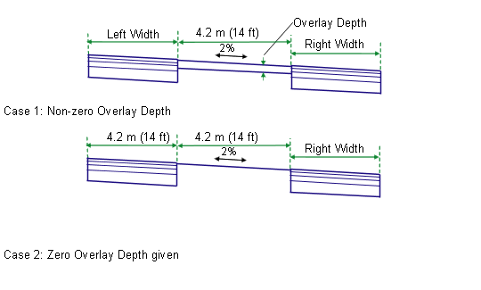
In layout mode, this subassembly is attached to any convenient point. The overlay layer is shown at a uniform depth for a width of 4.2 meters or 14 feet at a slope of -2%. The widening lanes extend from the edges-of-overlay at the given widths and depths at the -2% slope.
In modeling mode the subassembly adjusts to the positions and slopes determined by the Insert Points and the Existing Surface.

Point, Link, and Shape Codes
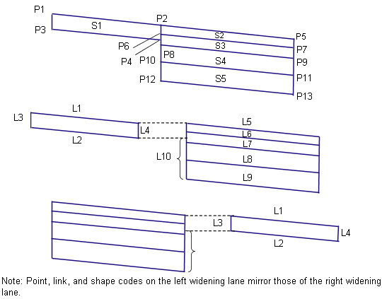
The following table lists the point, link, and shape codes for this subassembly that have codes assigned to them. Point, link, or shape codes for this subassembly that do not have codes assigned are not included in this table.
|
Point, Link, or Shape |
Code |
Description |
|---|---|---|
|
P5 |
ETW |
Outside edge of widening lane on finish grade |
|
P7 |
ETW_Pave1 |
Outside edge of widening lane on Pave1 |
|
P9 |
ETW_Pave2 |
Outside edge of widening lane on Pave2 |
|
P11 |
ETW_Base |
Outside edge of widening lane on Base |
|
P13 |
ETW_Sub |
Outside edge of widening lane on Subbase |
|
L1, L5 |
Top, Pave |
Finish grade surface |
|
L2 |
Overlay |
Superimposed over links on the Existing Surface. Note that there may be more than a single link between points P3 and P4. |
|
L6 |
Pave1 |
|
|
L7 |
Pave2 |
|
|
L8 |
Base |
|
|
L9 |
SubBase, Datum |
|
|
L10 |
Datum |
|
|
S1 |
Overlay |
Area between the overlay and existing lane |
|
S2 |
Pave1 |
|
|
S3 |
Pave2 |
|
|
S4 |
Base |
|
|
S5 |
SubBase |
Coding Diagram
