This subassembly inserts a paved shoulder with all layers including subbase extended to a daylight point. Optionally you can reduce the depths of various sublayers to interlace subbase material around some of the select material layers.
Attachment
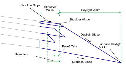
The attachment point is at the inside edge of the paved shoulder, which is typically at the outside edge-of-traveled way.
Input Parameters
Note: All dimensions are in meters or feet unless otherwise noted. All slopes are in run-over-rise form (for example, 4 : 1) unless indicated as a percent slope with a “%” sign.
| Parameter | Description | Type | Default |
|---|---|---|---|
| Side |
Specifes to insert the subassembly either on the right or the left side of the attachment point. |
Left/Right | Right |
| Shoulder Width | Width from the attachment point to the shoulder hinge point. | Numeric |
2.4 m 8.0 ft |
| Use Superelevation Slope | Specifies to use the slope from the superelevation specification defined on the baseline alignment. |
Selection List:
|
No |
| Shoulder Slope Direction |
Specifies whether the shoulder slopes away from the crown or towards the crown |
Selection List:
|
Away from Crown |
| Default Shoulder Slope | Default cross slope of the shoulder surface. This value is used if superelevation slope is not used, or is not specified for the baseline alignment. | Numeric | -4.0% |
| Subbase Daylight Type | Select whether to hold the daylight link to a fixed slope with variable width, or hold it to a fixed width with variable slope | Selection list: a) Hold Slope, Adjust Width, b) Hold Width, Adjust Slope | Hold Slope, Adjust Width |
| Daylight Slope / Width | The value of the fixed width or fixed slope (x : 1) of the daylight link. | Numeric, positive | 4 ( : 1) |
| Subbase Superelevation | Specifies to use the slope from the superelevation specification defined on the baseline alignment. | List of options: a.) No, b.) Outside shoulder slope, c.) Inside shoulder slope | No |
| Default Subbase Slope | Default cross slope of the subbase surface. This value is used if superelevation slope is not used, or is not specified for the baseline alignment. | Numeric | -4.0% |
| Pave1 Depth | Depth between finish grade and Pave1 (zero to omit) | Numeric, non-negative |
0.025 m (0.083 ft) |
| Gap between Pave1 and Pave 2 | Depth reduction of Pave1 to interlace subbase material between Pave1 and Pave2 | Numeric, positive |
0.000m 0.000 ft |
| Pave2 Depth | Depth second level pavement material (zero to omit) | Numeric, non-negative |
0.025 m 0.083 ft |
| Pave2 Trim | Reduced width of Pave 2 material to enable subbase interlacing. Side edge of the material layer will have same slope as shoulder daylight slope. | Numeric, positive |
0.4 m 1.32 ft |
| Gap between Pave2 and Base | Depth reduction of pave2 to interlace subbase material between Pave2 and Base Course | Numeric, positive |
0.01 m (.033 ft |
| Base Depth | Depth of base course (between Pave2 and Base; zero to omit) | Numeric, non-negative |
0.100 m 0.333 ft |
| Base Trim | Reduced width of Base course material to to enable subbase interlacing. Side edge of the material layer will have same slope as shoulder daylight slope. | Numeric, positive |
0.4 m 1.32 ft |
| Subbase Depth | Depth of the subbase layer at the attachment point from bottom of base course (zero to omit) | Numeric, non-negative |
0.300 m 1.0 ft |
| Topsoil Thickness | Specifies depth of material lining along daylight link. If a value of ZERO is entered - then no lining material is added. | Numeric, non-negative | 0.0 |
| Topsoil Shape Code | Specifies shape code for the topsoil material | String | Topsoil |
| Pave1 Shape Code | Specifies shape code for the top layer (below topsoil if enabled) material | String | Pave1 |
| Pave2 Shape Code | Specifies shape code for the second layer material (above base course) | String | Pave2 |
Target Parameters
This section lists the parameters in this subassembly that can be mapped to one or more target objects, such as a surface, alignment, or profile object in a drawing. For more information, see To Specify Corridor Targets.
| Parameter | Description | Status |
|---|---|---|
| Shoulder Width | Can be used to override the fixed Shoulder Width and tie the edge-of-shoulder to an offset alignment. The following object types can be used as targets for specifying this offset: alignments, polylines, features lines, or survey figures. | Optional |
Output Parameters
| Parameter | Description | Type |
|---|---|---|
| Daylight Slope | Slope of the daylight link | Numeric |
| Daylight Offset | Offset of the subgrade daylight point | Numeric |
| Daylight Elevation | Elevation of the subgrade daylight point | Numeric |
| Shoulder Width | Width of the paved shoulder | Numeric |
| Shoulder Slope | Slope of the paved shoulder | Numeric |
Behavior
The finish grade of the shoulder is inserted for the given Shoulder Width and Default Shoulder Slope outward from the attachment point. The subbase link is inserted from the attachment point starting at the Subbase Depth below the finish grade.
The shoulder daylight link can be inserted with either a fixed slope (Hold Daylight Slope = True), or a fixed width (Hold Daylight Slope = False). If a fixed slope is used, the daylight link is extended from the outside edge of the shoulder until it intersects the subbase link. Otherwise, the subbase layer is extended for the Daylight Width beyond the outside edge of the shoulder, and the daylight link is connected to the end of the subbase.
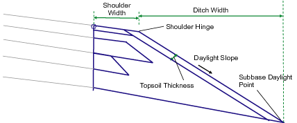
If topsoil material is set to “a positive” value then a new material layer is introduced to the specified thickness right below the daylight link. The thickness is measured perpendicular to the shoulder daylight ink. This layer extends from the top layer of the shoulder to the subgrade daylight link at the bottom. Due to this new layer provision, width of the shoulder top layer will be adjusted as shown in the following illustration.
The Pave1, Pave2, and Base surface links are inserted parallel to the finish grade at the given depths until they intersect with the shoulder daylight link.
If the above trim values are set for a positive value then top of respective material will be shortened by that value and the bottom link will be derived with material side slope equal to the daylight slope.
Further, if the “gap between Pave1/Pave2 and/or Pave2/Base” is set to a positive value – then those lavers will be separated by that gap as shown in the illustration below.
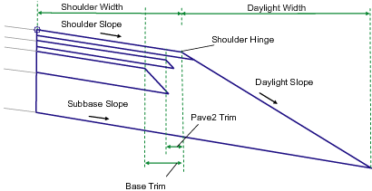
If the gaps between Pave1/Pave2 and Pave2/Base are set to ZERO then the subassembly will be drawn as shown below.
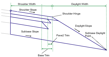
If the sub-layers are set with zero trim values, then this subassembly will be similar to the ShoulderExtendAll subassembly with optional topsoil lining.
Layout Mode Operation
In layout mode this subassembly displays the links comprising the shoulder with default parameters assigned to it.
Point, Link, and Shape Codes
The following table lists the point, link, and shape codes for this subassembly that have codes assigned to them. Point, link, or shape codes for this subassembly that do not have codes assigned are not included in this table.
| Type | Codes | Description |
|---|---|---|
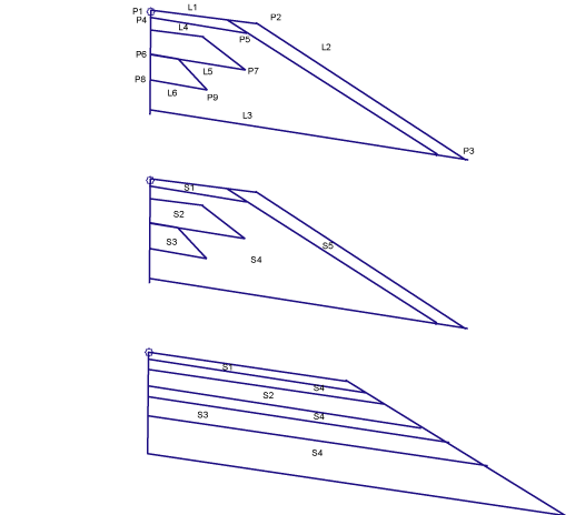
| P2 | EPS | Edge of paved shoulder, finish grade |
| P3 | Daylight_Sub | Subbase daylight point |
| P5 | EPS_Pave1 | Edge of paved shoulder on Pave1 |
| P7 | EPS_Pave2 | Edge of paved shoulder on Pave2 |
| P9 | EPS_Base | Edge of paved shoulder on Base |
| L1, L2 | Top | Finish grade of the shoulder |
| L4 | Pave1 | |
| L5 | Pave2 | |
| L6 | Base | |
| L3 | Datum, SubBase | |
| S1 | User Defined Code | User defined code for top layer of shoulder (default - Pave1) |
| S2 | User Defined Code | User defined code for second layer of shoulder (default - Pave2) |
| S3 | Base | |
| S4 | SubBase | |
| S5 | User Defined Code | User defined code for topsoil material (default - Topsoil) |
Coding Diagram
