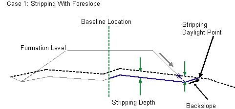
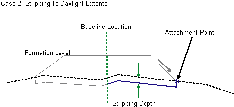
This subassembly is used to specify the existing top layer stripping to a specified depth.


Optionally, this subassembly can extend the stripping back to the existing ground with a specified backslope.
Attachment
The attachment point is at the daylight point on the finish grade.
Input Parameters
Note: All dimensions are in meters or feet unless otherwise noted. All slopes are in run-over-rise form (for example, 4 : 1), unless indicated as a percent slope with a “%” sign.
| Parameter | Description | Type | Default |
|---|---|---|---|
| Stripping Depth | Specifies depth of the topsoil to remove. | Numeric |
0.05m 0.167ft |
| Extend to Existing Ground | Specifies to extend the stripping back to existing ground | Boolean | Yes |
| Foreslope | Default foreslope of the stripping extension from original daylight point to beginning of back slope. | Numeric | -2 (:1) |
| Backslope | Backslope to grade from bottom of stripping back into the existing ground | Numeric, positive | 2 (:1) |
Target Parameters
This section lists the parameters in this subassembly that can be mapped to one or more target objects, such as a surface, alignment, or profile object in a drawing. For more information, see To Specify Corridor Targets.
| Parameter | Description | Status |
|---|---|---|
| Existing Surface | Name of the existing surface to grade back from bottom of stripping. The following object types can be used as targets for specifying this surfaces: surfaces. | Required |
Output Parameters
None.
Behavior
This subassembly inserts parallel links defining the bottom of the stripping layer below a specified surface. If the option to extend stripping to the existing ground with a backslope is set to No, then stripping starts at the attachment point directly on the specified surface, with a vertical link with depth value specified in the input parameters. From the bottom of this vertical link, a series of links parallel to the specified surface are introduced inwards, until the baseline location of the assembly. If the option to extend stripping to the existing ground is set to Yes, then at the attachment point, a link is introduced with the specified foreslope, until the elevation difference between the bottom of this new link and the specified existing ground is equal to the “stripping depth”. From this point, a series of links parallel to the specified surface are introduced inwards, until the baseline location of the assembly. Additionally, another link outwardly is added to daylight to existing ground.
Layout Mode Operation
In layout mode, this subassembly inserts a horizontal line below the attachment point, towards the baseline location. This link is inserted from the attachment point at a depth equal to the “stripping depth”.
If the option to extend the stripping link to a surface is selected, then a foreslope link with a specified slope value to the stripping depth is inserted first, and then the horizontal link is added, as explained previously. Also, a backslope link is added outward, from the outside bottom of the stripping link with a specified foreslope, and to the elevation equal to the subassembly attachment point.
Point, Link, and Shape Codes
The following table lists the point, link, and shape codes for this subassembly that have codes assigned to them. Point, link, or shape codes for this subassembly that do not have codes assigned are not included in this table.
| Point/Link | Codes | Description |
|---|---|---|
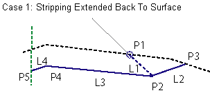
| P3 | Daylight_Strip (Only for Case 1) | Daylight point of stripping backslope link |
| L1 | Foreslope_Stripping (Only for case 1) | Stripping foreslope link defining backfill |
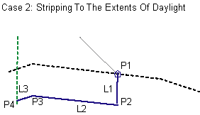
| L2, L3, L4… Ln | Stripping | Stripping links |
Coding Diagram

