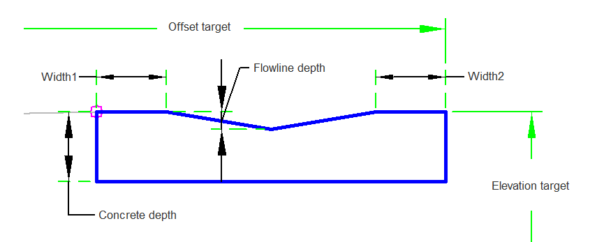
The ValleyGutterSimple subassembly is a concrete valley gutter with user defined widths, concrete depths, and flow line depth. The width can be modified and the flowline stays at the center.

Attachment
The attachment point is at the inside edge of the valley gutter.
Input Parameters
|
Parameter |
Description |
Type |
Default |
|---|---|---|---|
| Side | Specifies which side to place the subassembly. | Left/Right | Right |
| Concrete Width | Width of the concrete gutter. | Numeric, positive |
5 ft 1.5 m |
| Flowline Depth | Depth of the valley gutter from the top of the ditch to the flowline. | Numeric, positive |
0.08 ft 0.02 m |
| Width1 | Width of the valley gutter on the side of the attachment point. | Numeric, positive |
0.5 ft 0.15 m |
| Width2 | Width of the valley gutter on the opposite side of the attachment point. | Numeric, positive |
0.5 ft 0.15 m |
| Concrete Depth | Depth of the concrete measured from the attachment point. | Numeric, positive |
0.75 ft 0.2 m |
Target Parameters
This section lists the parameters in this subassembly that can be mapped to one or more target objects. For more information, see To Specify Corridor Targets.
|
Parameter |
Description |
Status |
|---|---|---|
|
Target Offset |
May be used to override the fixed Width and tie the edge-of-shape to an offset aligning. The following object types can be used as targets for specifying this offset: alignments, polylines, features lines, or survey figures. | Optional |
|
Flowline Elevation |
May be used to override the flowline depth and tie the flowline elevation to the elevation of a profile. The following object types can be used as targets for specifying this elevation: profiles, 3D polylines, feature lines, or survey figures. | Optional |
Runtime Logical Assignments
None.
Output Parameters
None.
Behavior
This subassembly will insert a simple valley gutter. The location of the width of the subassembly can be specified with a fixed width, or with an optional alignment. The valley gutter can be specified with a fixed depth, or a profile can be assigned to control the depth.
Layout Mode Operation
In layout mode the subassembly displays the links comprising the valley gutter with the user input values.
Point, Link, and Shape Codes
The following table lists the point, link, and shape codes for this subassembly that have codes assigned to them. Point, link, or shape codes for this subassembly that do not have codes assigned are not included in this table.
|
Point, Link, or Shape |
Code |
Description |
|---|---|---|
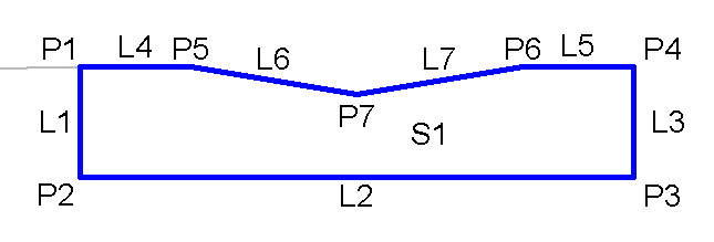
| P1 | Top, Hinge | |
| P2 | Datum | |
| P3 | Datum, Concrete | |
| P4 - P6 | Top | |
| P7 | Flowline, Top | |
| L1, L3 | Concrete | |
| L2 | Datum, Concrete | |
| L4 - L7 | Top | |
| S1 | ValleyGutter |
Coding Diagram
