This subassembly adds an overlay layer on an existing crowned roadway, with either a leveling and milling layer added as required.

Attachment
The attachment point is the crown point on the overlay finish grade.
Input Parameters
Note: All dimensions are in meters or feet unless otherwise noted. All slopes are in run-over-rise form (for example, 4 : 1) unless indicated as a percent slope with a “%” sign.
|
Parameter |
Description |
Type |
Default |
|---|---|---|---|
|
Crown Point Offset |
Offset of the crown point. The crown and sample points are used to calculate the left and right slopes of the existing roadway. |
Numeric |
0.0 |
|
Left Sample Point Offset |
Offset of the left sample point |
Numeric |
0.0 |
|
Right Sample Point Offset |
Offset of the right sample point |
Numeric |
0.0 |
|
Left Trim Point |
Offset of the left trim point, which defines the outside edge of the overlay layer on the left side |
Numeric |
0.0 |
|
Right Trim Point |
Offset of the right trim point, which defines the outside edge of the overlay layer on the right side |
Numeric |
0.0 |
|
Left Overlay Slope Options |
Specifies the left overlay slope with the following options: a) user defined, b) to match slope from inside sample point to outside sample point or, c) use the outside lane superelevation slope of the baseline alignment. |
Selection list |
Match slope |
|
Default Left Overlay Slope |
Specifies user defined slope. Also can be used if match points or superelevation slope doesn’t return appropriate value. |
Numeric, grade |
- 2.0 % |
|
Right Overlay Slope Options |
Specifies the right overlay slope with the following options: a) user defined, b) to match slope from inside sample point to outside sample point or, c) use the outside lane superelevation slope of the baseline alignment. |
Selection list |
Match slope |
|
Default Right Overlay Slope |
Specifies user defined slope. Also can be used if match points or superelevation slope doesn’t return appropriate value. |
Numeric, grade |
- 2.0 % |
|
%Slope Tolerance |
The value that the Overlay Slopes are allowed vary from their design values. The slope tolerance is not used if the Overlay Slope is given as M (see Behavior below for details). |
Numeric, positive |
0.5% |
|
Use Profile |
Selects whether to hold the top of overlay at the inside trim point to the corridor profile elevation, or to set the vertical placement of the overlay layer based on the Minimum Clearance value |
Selection List |
Use minimum clearance |
|
Minimum Clearance (+/-) |
The minimum vertical clearance between the existing surface and the bottom of the overlay layer. A positive value places the bottom-of-overlay link above the existing surface, creating a Leveling layer beneath the overlay. A negative value places the bottom-of-overlay link below the existing surface, creating a Milling layer that coincides with a portion of the Overlay layer. |
Numeric |
0.100 m 0.30 ft |
|
Overlay Depth |
The thickness of the overlay layer |
Numeric, positive |
0.100 m 0.30 ft |
Target Parameters
This section lists the parameters in this subassembly that can be mapped to one or more target objects, such as a surface, alignment, or profile object in a drawing. For more information, see To Specify Corridor Targets.
|
Parameter |
Description |
Status |
|---|---|---|
|
Existing Surface |
Name of the Surface defining the existing roadway. The following object types can be used as targets for specifying this surface: surfaces. |
Required |
|
Crown Point Offset |
May be used to override the fixed Crown Point Offset and tie the point to an offset alignment. The following object types can be used as targets for specifying this offset: alignments, polylines, feature lines, or survey figures. |
Optional |
|
Left Sample Point Offset |
May be used to override the fixed Left Sample Point Offset and tie the point to an offset alignment. The following object types can be used as targets for specifying this offset: alignments, polylines, feature lines, or survey figures. |
Optional |
|
Right Sample Point Offset |
May be used to override the fixed Right Sample Point Offset and tie the point to an offset alignment. The following object types can be used as targets for specifying this offset: alignments, polylines, feature lines, or survey figures. |
Optional |
|
Left Trim Point Offset |
May be used to override the fixed Left Trim Point Offset and tie the point to an offset alignment. The following object types can be used as targets for specifying this offset: alignments, polylines, feature lines, or survey figures. |
Optional |
|
Right Trim Point Offset |
May be used to override the fixed Right Trim Point Offset and tie the point to an offset alignment. The following object types can be used as targets for specifying this offset: alignments, polylines, feature lines, or survey figures. |
Optional |
Output Parameters
|
Parameter |
Description |
Type |
|---|---|---|
|
Superelevation Axis of Rotation |
Indicates whether the subassembly supports the axis of rotation calculation. To view a description of the parameter, in the Properties window, hover the cursor over the parameter. For more information, see Profile Grade Line Adjustments During Superelevation. |
Static (Description) |
|
Left Overlay %Slope |
The slope used for applying the overlay layer on the left side |
Numeric |
|
Right Overlay %Slope |
The slope used for applying the overlay layer on the right side |
Numeric |
Behavior
This subassembly inserts parallel links defining the top and bottom of an overlay layer on each side that join at the crown point. The links are inserted from the Crown Point Offset to the Left and Right Trim Offsets.
Overlay Slopes
The slope of the Existing Surface on each side is determined betweenthe crown and sample points. The slopes of the overlay layers aredetermined by the following steps:
- If the Overlay %Slope input is given as M, then the overlay slope matches the slope from the Crown Point to the Sample point.
- If the Overlay %Slope is given as S, then the overlay uses the outside lane superelevation slope defined for the corridor alignment.
- If a numeric value is given for the Overlay %Slope, the given value is used.
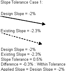
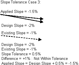
- If a numeric value or the superelevation slope is used, the overlay slope is compared to the existing slope between the sample points. If the difference exceeds the Slope Tolerance value, the design slope is adjusted up or down by the Tolerance value to make it more closely match the existing slope and minimize the amount of leveling or milling. Slope adjustment does not occur if the Slope Tolerance is zero.


Overlay Elevations
The elevations of the overlay points are determined as follows:
- If the Use Profile value is True, the elevation of the corridor profile is held at the Crown Point offset on the top of overlay. The overlay is extended to each side at the overlay slopes to the Left and Right Trim offsets, and parallel links are inserted for the bottom-of-overlay. Any areas above the existing surface and below the bottom-of-overlay are stored as closed shapes with code “Level”. Areas below the existing surface and above the bottom-of-overlay are stored as closed shapes with code “Mill”.
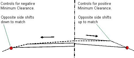
- If the Use Profile value is False, the bottom-of-overlay link on each side is shifted vertically to hold to the Minimum Clearance above or below the existing surface. A positive Minimum Clearance creates a leveling area above the existing surface and below the bottom-of-overlay. A negative clearance creates a milling area below the existing surface and above the bottom-of-overlay. The overlay links on one side are shifted vertically so that the links meet at the crown point.
Minimum Clearance Point
The method of determining the point where the Minimum Clearance applies is shown in the diagram below.
- A vertical projection line is established at any arbitrary offset.
- Each point on the Existing Surface between the two trim points is projected back to the projection line at the Overlay Slope.
- The point with the highest elevation on the projection line is the control point for a Minimum Clearance value greater than zero. The one with the lowest is the control point for a Minimum Clearance value less than zero.

Layout Mode Operation
In layout mode, this subassembly displays the overlay layer positioned from any convenient point of attachment at a slope of -2%.
Point, Link, and Shape Codes
The following table lists the point, link, and shape codes for this subassembly that have codes assigned to them. Point, link, or shape codes for this subassembly that do not have codes assigned are not included in this table.
|
Point, Link, or Shape |
Code |
Description |
|---|---|---|
|
P1 |
Crown |
Crown on finish grade |
|
P2, P3 |
EOV |
Overlay edges on finish grade |
|
P4 |
Crown_Overlay |
Crown on bottom-of-overlay |
|
P5, P6 |
EOV_Overlay |
Edges of bottom-of-overlay |
|
L1, L2 |
Top, Pave |
Top of overlay |
|
L3 – L6 |
Overlay |
Overlay links. Note that L5, L6 go from the bottom-of-overlay to top-of-overlay in both the Leveling and Milling cases. |
|
L7, L8 |
Level Mill |
Verticals from existing surface to bottom-of-overlay: Level - For the Leveling case. Mill - For the Milling case. |
|
S1 |
Overlay |
Area between the top and bottom of overlay. This overlaps the milling area (S3) for the Milling case as shown below. |
|
S2 |
Level |
Area above existing surface and below the bottom of overlay (Leveling case) |
|
S3 |
Mill |
Area below the existing surface and above the bottom of overlay (Milling case). This area overlaps the Overlay area as shown below. |
Coding Diagram
