This subassembly creates a cross-sectional representation of a depressed median between the attachment point and a previously named marked point.
Use the MarkPoint subassembly first if the connecting point has not already been marked.

Attachment
The attachment point is at the outside edge of either the left or right median ditch slope, and the previously defined marked point must be on the opposite outside edge. It does not matter which point is left or right of the other.
Input Parameters
Note: All dimensions are in meters or feet unless otherwise noted. All slopes are in run-over-rise form (for example, 4 : 1) unless indicated as a percent slope with a “%” sign.
|
Parameter |
Description |
Type |
Default |
|---|---|---|---|
|
Marked Point Name |
Name of the previously defined marked point |
String |
None |
|
Slope 1 |
Slope (x : 1) of the link extending inward from the attachment point |
Numeric |
-4 ( : 1) |
|
Slope 2 |
Slope (x : 1) of the link extending inward from the marked point |
Numeric |
-4 ( : 1) |
|
Hold Ditch Slopes |
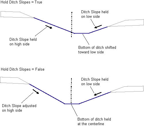
For the cases where the top-of-ditch-slope points are at unequal elevations, selects whether to hold the ditch sideslopes and let the position of the ditch shift, or to hold the ditch at the center and adjust the sideslope on the high side. |
Selection list |
Hold ditch sideslopes, shift ditch from center |
|
Ditch Width |
Width of the bottom of the median ditch (zero for a V-ditch) |
Numeric, positive |
0.6 m 2 ft |
Target Parameters
This section lists the parameters in this subassembly that can be mapped to one or more target objects, such as a surface, alignment, or profile object in a drawing. For more information, see To Specify Corridor Targets.
Target Parameters: None.
Output Parameters
None.
Behavior
The locations of the attachment point and marked point are determined. The marked point may be either to the right or left of the attachment point. Links are extended inward at Slope 1 from the attachment point, and at Slope 2 from the marked point, until they intersect. If a ditch width is given, a horizontal bottom-of-ditch link is fit into the intersecting side slopes.
Ditch Slopes
The top of the ditch slopes may be at different elevations on the left and right sides, resulting in an asymmetrical ditch. There are two options for handling this situation. If Hold Ditch Slopes is set to True, then the Slope 1 and Slope 2 values are held on both sides, shifting the bottom of ditch away from the centerline towards the lower side. If set to False, the ditch bottom is centered about the midpoint offset between the tops-of-slopes, the given slope is held on the lower side, and the slope is adjusted to match on the higher side.

Superelevation Axis of Rotation Support
This subassembly works with all axis of rotation pivot methods.
Point, Link, and Shape Codes
The following table lists the point, link, and shape codes for this subassembly that have codes assigned to them. Point, link, or shape codes for this subassembly that do not have codes assigned are not included in this table.
|
Point, Link, or Shape |
Code |
Description |
|---|---|---|
|
P2 |
LMedDitch |
Left edge of median ditch |
|
P3 |
RMedDitch |
Right edge of median ditch |
|
L1 – L3 |
Top Datum |
Finish grade on unpaved shoulder and median links |
Layout Mode Operation
In layout mode, this subassembly calculates and displays the median links based on the input parameters given and the relative locations of the attachment point and marked point.
Coding Diagram
