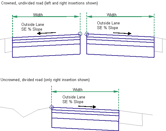
This subassembly creates a cross-sectional representation of a travel lane, applying the Outside or Inside Lane superelevation slope value for the corridor model’s baseline alignment.
It is used for most undivided roads, or divided roads with no lane slope break on either side. It may also be used for the outside or inside lanes of divided crowned or broken-back highways. The pavement structure follows the standards described in “Pavement Structure on Paved Sections” in the Autodesk Civil 3D Help.
Attachment
The attachment point is at the inside edge of the lane on the finish grade surface. This component can be attached to either the left or right side.
Input Parameters
Note: All dimensions are in meters or feet unless otherwise noted. All slopes are in run-over-rise form (for example, 4 : 1) unless indicated as a percent slope with a “%” sign.
|
Parameter |
Description |
Type |
Default |
|---|---|---|---|
|
Side |
Specifies which side to place the subassembly |
Left / Right |
Right |
|
Width |
Width of the lane from the offset of the inside edge to the offset of the outside edge |
Numeric, positive |
3.6 m 12.0 ft |
|
Default Slope |
Default slope of the lane to be used when the superelevation slope for the alignment is not defined |
Numeric |
-2.0 |
|
Pave1 Depth |
Thickness of the Pave1 layer (zero to omit) |
Numeric, non-negative |
0.025 m 0.083 ft |
|
Pave2 Depth |
Thickness of the Pave2 layer (zero to omit). |
Numeric, non-negative |
0.025 m 0.083 ft |
|
Base Depth |
Thickness of the base layer (zero to omit) |
Numeric, positive |
0.100 m 0.333 ft |
|
Subbase Depth |
Thickness of the subbase layer (zero to omit) |
Numeric, non-negative |
0.300 m 1.0 ft |
|
Use Superelevation |
Specifies to use superelevation slope for the lane |
Selection List:
|
None |
|
Slope Direction |
Specifies whether the lane slopes away from the crown or towards the crown |
Selection List:
|
Away from Crown |
|
Potential Pivot |
Specifies whether the inside and outside points are available for use as axis of rotation pivot points |
Selection List:
|
Yes |
|
Inside Point Code |
Specifies the point type for the inside edge of the lane |
Selection List:
|
Crown |
|
Outside Point Code |
Specifies the point type for the outside edge of the lane |
|
Edge of Pavement (ETW) |
Target Parameters
This section lists the parameters in this subassembly that can be mapped to one or more target objects. For more information, see To Specify Corridor Targets.
|
Parameter |
Description |
Status |
|---|---|---|
|
Lane Width |
May be used to override the fixed lane Width and tie the edge-of-lane to an offset alignment. The following object types can be used as targets for specifying the width: alignments, polylines, feature lines, or survey figures. |
Optional |
|
Outside Elevation |
May be used to override the normal lane slope and tie the outer edge of the travel lane to the elevation of a profile. The following object types can be used as targets for specifying the elevation: profiles, 3D polylines, feature lines, or survey figures. |
Optional |
Output Parameters
|
Parameter |
Description |
Type |
|---|---|---|
|
Lane Width |
Width of the lane |
Numeric |
|
Lane Slope |
% slope of the lane |
Numeric |
Behavior
The lane superelevation slope is obtained from the superelevation specifications for the baseline alignment. You can specify which superelevation slope is used for the lane.
Starting at the attachment point, a finish grade surface and parallel subgrade are inserted using the given width, depth, and the superelevation slope. Vertical links close the shape at either end of the lane.
If an offset horizontal alignment name is assigned to the Width during corridor modeling, the width of the lane will vary to match the offset of the alignment. This subassembly can be used in assemblies that accomodate axis of rotation pivot points in different crowned and planar roadway types. For more information, see To Work With Assemblies That Support Superelevation Axis of Rotation Pivot Points.
Layout Mode Operation
In layout mode, this subassembly displays all lane links using the width and depth input parameters at a -2% slope.
When Potential Pivot is set to Yes,
 markers indicate the potential pivot points on the inside and outside points.
Point, Link, and Shape Codes
The following table lists the point, link, and shape codes for this subassembly that have codes assigned to them. Point, link, or shape codes for this subassembly that do not have codes assigned are not included in this table.
|
Point, Link, or Shape |
Code |
Description |
|---|---|---|
|
P1 |
Crown |
Crown point on finish grade (optional) |
|
P2 |
ETW |
Inside edge of lane on finish grade |
|
P3 |
Crown_Pave1 |
Crown point on the Pave1 layer (optional) |
|
P4 |
ETW_Pave1 |
Inside edge of lane on Pave. |
|
P5 |
Crown_Pave2 |
Crown point on the Pave2 layer (optional) |
|
P6 |
ETW_Pave2 |
Inside edge of lane on Pave2 |
|
P7 |
Crown_Base |
Crown point on base grade (optional) |
|
P8 |
ETW_Base |
Inside edge of lane on Base |
|
P9 |
Crown_Sub |
Crown point on subbase grade (optional) |
|
P10 |
ETW_Sub |
Inside edge of lane on Subbase |
|
L1 |
Top, Pave |
Finish grade surface |
|
L2 |
Pave1 |
Pave1 surface |
|
L3 |
Pave2 |
Pave2 surface |
|
L4 |
Base |
Base surface |
|
L5 |
SubBase Datum |
Subbase surface |
|
S1 |
Pave1 |
Area between finish grade and Pave1 |
|
S2 |
Pave2 |
Area between Pave1 and Pave2 |
|
S3 |
Base |
Area between Pave2 and Base |
|
S4 |
SubBase |
Area between Base and Subbase |
Coding Diagram