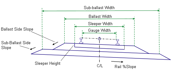
This subassembly inserts the rails, sleeper, ballast, and sub-ballast for a single-track railroad.
It should be followed with a Daylight subassembly on the left and right sides to close to existing ground in cut and fill situations.

This subassembly is designed for visualization and to demonstrate the use of corridor modeling for rail applications. It is not intended for actual engineering production work.
Attachment
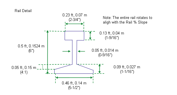
The attachment point is at a distance equal to the rail height above the centerline of the sleeper.
Input Parameters
Note: All dimensions are in meters or feet unless otherwise noted. All slopes are in run-over-rise form (for example, 4 : 1) unless indicated as a percent slope with a “%” sign.
|
Parameter |
Description |
Type |
Default |
|---|---|---|---|
|
Rail % Slope |
% slope of the roadbed |
Numeric |
0 (%) |
|
Gauge Width |
Width of the rail gauge from inside-to-inside rail. The rails are placed symetrically about the centerline alignment. |
Numeric, positive |
1.435 m 4.7083 ft (4’ 8-1/2”) |
|
Sleeper Width |
Width of the sleeper, placed symetrically about the centerline |
Numeric, positive |
2.4 m 8.0 ft |
|
Sleeper Height |
Height of the sleeper |
Numeric, positive |
0.200 m 0.67 ft |
|
Ballast Width |
Width of the top of the ballast layer, placed symetrically about the centerline |
Numeric, positive |
3.6 m 12.0 ft |
|
Ballast Depth |
Thickness of the ballast layer from finish grade |
Numeric, positive |
0.3 1.0 ft |
|
Ballast Side Slope |
Side slope (x : 1) of the ballast layer |
Numeric, positive |
2 (: 1) |
|
Sub-ballast Width |
Width of the top of the sub-ballast layer, placed symetrically about the centerline |
Numeric, positive |
6.6 m 22.0 ft |
|
Sub-ballast Depth |
Thickness of the sub-ballast layer |
Numeric, positive |
0.3 1.0 ft |
|
Sub-ballast Side Slope |
Side slope of the sub-ballast layer |
Numeric, positive |
2 (: 1) |
Target Parameters
This section lists the parameters in this subassembly that can be mapped to one or more target objects, such as a surface, alignment, or profile object in a drawing. For more information, see To Specify Corridor Targets.
Target Parameters: None.
Output Parameters
None.
Behavior
The links for the rails, sleeper, ballast, and sub-ballast are calculated and placed based on the input parameter values provided. If the Rail %Slope is non-zero, the corridor profile elevation is held at the center of the rail on the low side. The finish grade, sleeper, ballast, and sub-ballast links are maintained at the Rail %Slope.

Layout Mode Operation
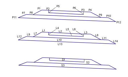
In layout mode, this subassembly displays the links comprising the finish grade, ballast, sub-ballast, and side slopes.

Constants
|
Point, Link, or Shape |
Constant |
Description |
|---|---|---|
|
P1, P4 |
EBS |
Edge of ballast shoulder |
|
P2, P3 |
ESL |
Edge of sleeper |
|
P8,P9 |
Daylight_Ballast |
Daylight point for the ballast layer |
|
P7, P10 |
ESBS |
Edge of subballast shoulder |
|
P11, P12 |
Daylight_Subballast |
Daylight point for the sub-ballast layer |
|
All rail points |
R1, R2, ..… |
Numbered sequentially for longitudinal connection (not shown in diagram) |
|
L1, L3 |
Top, Ballast |
Finish grade on ballast layer |
|
L2 |
Top, Sleeper |
Finish grade on top-of-sleeper |
|
L4, L6 |
Sleeper |
Sides of sleeper |
|
L7, L8 |
Top, Ballast |
Sideslopes on ballast layer (side slopes) |
|
L10 |
Ballast |
Bottom of ballast |
|
L9, L11, L12, L14 |
Top, Subballast |
Finish grade on subballast layer |
|
L13 |
Subballast |
Bottom of subballast |
|
S1 |
Sleeper |
|
|
S2 |
Ballast |
|
|
S3 |
Subballast |
|
|
Rail shapes |
Rail |
Not shown in diagram |
Coding Diagram
