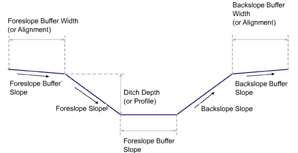
This subassembly inserts a flat or V-shaped ditch with user-defined horizontal and vertical control parameters.
This subassembly can also include an optional lining material.
Attachment
The attachment point is at the inside edge of the first link. This will be either the inner buffer or the foreslope link of the ditch if the inner buffer width is zero. This is typically connected to the outside edge of a shoulder.
Input Parameters
Note: All dimensions are in meters or feet unless otherwise noted. All slopes are in run-over-rise form (for example, 4 : 1) unless indicated as a percent slope with a “%” sign.
| Parameter | Description | Type | Default |
|---|---|---|---|
| Side | Specifies side to insert subassembly | Left/Right | Right |
| Include Ditch | Specifies to use the ditch in cut and fill, fill only or cut only | Selection list: a)Cut/Fill, b) Cut, c) FIll | Cut/Fill |
| Ditch Width | Width of the bottom of ditch. Use zero for a V-shaped ditch. | Numeric, positive |
1 m 3 ft |
| Ditch Depth | Depth of Ditch | Numeric, positive |
1 m 3 ft |
| Foreslope Slope | Slope of the front-of-ditch link (x : 1). This link is always inserted downwards. | Numeric, positive | 4 ( : 1) |
| Foreslope Buffer Width | Allows a Buffer to be placed before the Foreslope (zero to omit) | Numeric, positive |
1 m 3 ft |
| Foreslope Buffer Slope | Slope of the foreslope buffer | Numeric, positive | -6 (:1) |
| Backslope Slope | Slope of the back-of-ditch link (x : 1). This link is always inserted upwards. | Numeric, positive | 4 ( : 1) |
| Backslope Buffer | Allows a Buffer to be placed backslope the backslope (zero to omit) | Numeric, positive |
1 m 3 ft |
| Backslope Buffer Slope | Slope of the backslope buffer | Numeric, positive | 6 (:1) |
| Place Lined Material | Specifies to place optional material lining along daylight links. You can choose All Links or None. | String | None |
| Slope Limit 1 | Specifies the slope limit until which the associated material lining is placed | Slope | 1 : 1 |
| Material 1 Thickness | Specifies the thickness of lined material. This thickness is measured perpendicular to the side of the slope. | Numeric, positive | 12 inches |
| Material 1 Name | Specifies the name of the material applies for lining along grading links | String | Rip Rap |
| Slope Limit 2 | Specifies the slope limit until which the associated material lining is placed | Slope | 2 : 1 |
| Material 2 Thickness | Specifies the thickness of lined material. This thickness is measured perpendicular to the side of the slope. | Numeric, positive | 6 inches |
| Material 2 Name | Specifies the name of the material applies for lining along grading links | String | Rip Rap |
| Slope Limit 3 | Specifies the slope limit until which the associated material lining is placed | Slope | 4 : 1 |
| Material 3 Thickness | Specifies the thickness of lined material. This thickness is measured perpendicular to the side of the slope. | Numeric, positive | 4 inches |
| Material 3 Name | Specifies the name of the material applies for lining along grading links | String | Seeded Grass |
Target Parameters
This section lists the parameters in this subassembly that can be mapped to one or more target objects, such as a surface, alignment, or profile object in a drawing. For more information, see To Specify Corridor Targets.
| Parameter | Description | Status |
|---|---|---|
| Ditch Inner Edge Alignment | May be used to override the fixed width of the foreslope buffer. The following object types can be used as targets for specifying this: alignments, polylines, feature lines, or survey figures. | Optional |
| Ditch outer edge Alignment | May be used to override the fixed width of the backslope buffer. The following object types can be used as targets for specifying this: alignments, polylines, feature lines, or survey figures. | Optional |
| Ditch Bottom Profile | May be used to override the fixed foreslope and backslope widths. The following object types can be used as targets for specifying this elevation: profiles, 3D polylines, feature lines, or survey figures. | Optional |
| Target Surface | Surface used to determine if the ditch is in cut or fill. The following object types can be used as targets for specifying this surface: surfaces. | Optional |
Output Parameters
None.
Behavior
This subassembly will insert a simple ditch shape (either flat bottom or V-shaped ditch) with optional foreslope and backslope buffers. The location of the inner ditch edge can be specified with a fixed width, or with an optional alignment. The ditch depth can be specified with a fixed height, or a profile can be assigned to control the depth. The Cut/Fill Test point is P3. Depending on the Include Ditch input parameter, the ditch will only be placed in cut, fill, or both cut and fill.
In Civil 3D 2010 and previous versions, the Material Thickness parameter was measured vertically. In Civil 3D 2011 and later, this parameter is measured perpendicular to the link. Therefore, if you open a drawing containing these subassemblies that was created in Civil 3D 2010 or prior in Civil 3D 2011 or later, and then rebuild the corridor(s), this parameter will be changed to reflect the new behavior. Any volume reports that use this subassembly will be updated to reflect the new behavior.
Layout Mode Operation
In layout mode, this subassembly displays all of the links comprising the ditch with the parameters set as input by the user.
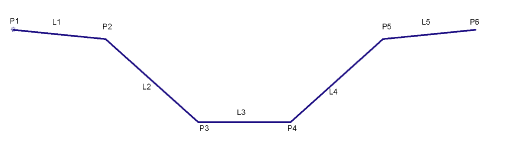
Point, Link, and Shape Codes
The following table lists the point, link, and shape codes for this subassembly that have codes assigned to them. Point, link, or shape codes for this subassembly that do not have codes assigned are not included in this table.
| Point, Link, or Shape | Codes | Description |
|---|---|---|
| P2 | Hinge | |
| P3 | Ditch_In | Inside bottom of ditch |
| P4 | Ditch_Out | Outside bottom of ditch |
| P5 | Hinge | |
| L1-5 | Top Datum | |
| L2,L4 | Slope_Link | |
| L3 | Ditch | Ditch Bottom |
Coding Diagram