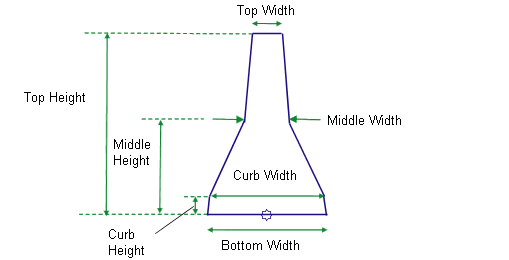
This subassembly creates a two-sided New Jersey barrier on a roadway surface.

Attachment
The attachment point is at the center of the bottom of the barrier.
Input Parameters
Note: All dimensions are in meters or feet unless otherwise noted. All slopes are in run-over-rise form (for example, 4 : 1) unless indicated as a percent slope with a “%” sign.
|
Parameter |
Description |
Type |
Default |
|---|---|---|---|
|
Top Width |
Width of the top of the barrier |
Numeric, positive |
0.15 m 0.5 ft |
|
Middle Width |
Width of the middle of the barrier |
Numeric, positive |
0.225 m 0.75 ft |
|
Bottom Width |
Width of the bottom of the barrier |
Numeric, positive |
0.6 m 2.0 ft |
|
Top Height |
Height to the top of the barrier |
Numeric, positive |
0.9 m 3.0 ft |
|
Middle Height |
Height to the middle of the barrier |
Numeric, positive |
0.45 m 1.5 ft |
|
Curb Height |
Height of the barrier curb |
Numeric, positive |
0.075 m 0.25 ft |
|
Curb Width |
Width at the top of the barrier curb |
Numeric, positive |
0.6 m 1.9 ft |
Output Parameters
None.
Target Parameters
This section lists the parameters in this subassembly that can be mapped to one or more target objects. For more information, see To Specify Corridor Targets.
Target Parameters: None.
Behavior
The subassembly constructs the shape of a two-sided New Jersey barrier, with the base centered about the attachment point.
Layout Mode Operation
In layout mode, this subassembly draws the barrier shape as specified by the input parameters.
Point, Link, and Shape Codes
The following table lists the point, link, and shape codes for this subassembly that have codes assigned to them. Point, link, or shape codes for this subassembly that do not have codes assigned are not included in this table.
|
Point, Link, or Shape |
Codes |
Description |
|---|---|---|
|
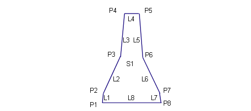
P1 - P8 |
P1, P2, ... P8 |
|
|
All links |
Barrier |
|
|
S1 |
Barrier |
Coding Diagram
