Point: Interpolate
Add a point that is located at an interpolated distance between a starting point and a destination point.
Properties
Specify the following parameters in the Properties panel.
| Point | |
| Point Number | Specifies the point number. You can change the automatically generated Point Number value. |
| Point Codes | Specifies the codes assigned to the point. |
| Point Geometry Type | |
| Type | Specifies the point type: |
| Point Geometry Properties | |
| From Point | Specifies the point to which the other geometry property values are relative. |
| Destination Point | Specifies the destination point. |
| Interpolate Parameter | Specifies the interpolated distance between the From Point and Destination Point at which to draw the point. Click [...] to open the Expression Editor, where you can enter or calculate a value. |
| Link | |
| Add Link To From Point | Draws a link from the point specified in the From Point row to the current point. |
| Name | Specifies the name of the link. |
| Codes | Specifies the codes assigned to the link. |
| ApplyAOR |
Specifies whether superelevation or cant will be applied to the link. Note: The ApplyAOR check box affects how the subassembly is previewed in the Subassembly Composer and how the subassembly behaves when it is used in Autodesk Subassembly Composer. You can use the Superelevation tab or the Cant tab to define values for previewing the superelevation or cant effect for the subassembly in the Preview panel. You can use the Input/Output Parameters tab to add parameters that are brought into Autodesk Subassembly Composer when the subassembly is imported.
|
| Miscellaneous | |
| Comment | Indicates notes about the point. Comments can be displayed in the Preview panel. |
Examples
To see examples of how this geometry element is used, open the following Sample PKT file:
Point Interpolate Point Example.pkt
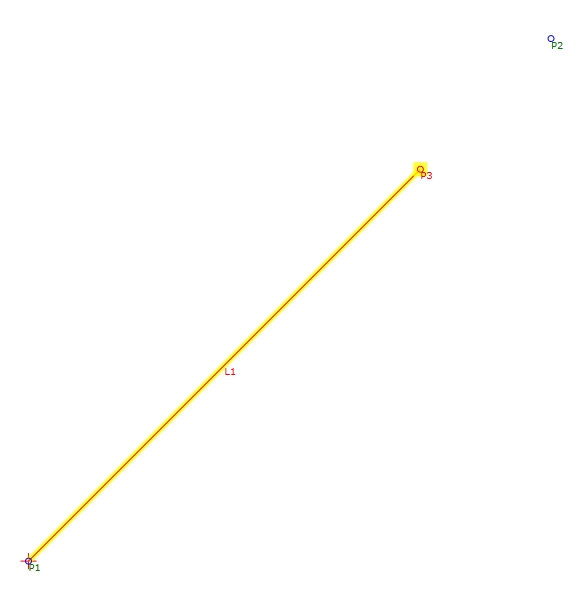
In the example, P3 is 75% of the distance between points P1 and P2.
To review the parameters, select Interpolate Point in the Flowchart, and then see the Point Geometry Properties section of the Properties panel.