Shape
Shape
Use a shape to create a closed cross sectional area that defines the material used in a given area of a subassembly.
Properties
Specify the following parameters in the Properties panel.
| Shape | |
| Shape Number | Specifies the shape number. You can change the automatically generated Shape Number value. |
| Shape Codes | Specifies the codes assigned to the shape |
| Component | |
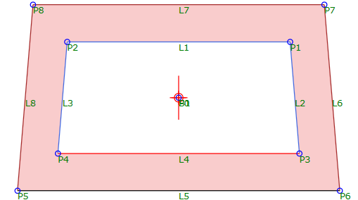
| Links | Specifies the links that enclose the shape. Click Add Link to add links from the current branch of the Flowchart. Click
 to pick a closed area from the Preview panel. to pick a closed area from the Preview panel. Note: You can select a closed area that encloses another area in order to create a shape with an empty area, as shown in the following illustration:
|
| Miscellaneous | |
| Comment | Indicates notes about the shape. Comments can be displayed in the Preview panel. |
Note: If Event Viewer displays a message stating that the shape is not closed, it is usually because two points overlap. For example, if two points are in the same location, and the intersecting links are each attached to a different point, the shape is not closed. To close a shape, intersecting links must be attached to the same point.
Examples
To see an example of how this geometry element is used, open the following Sample PKT file:
Shape Example.pkt
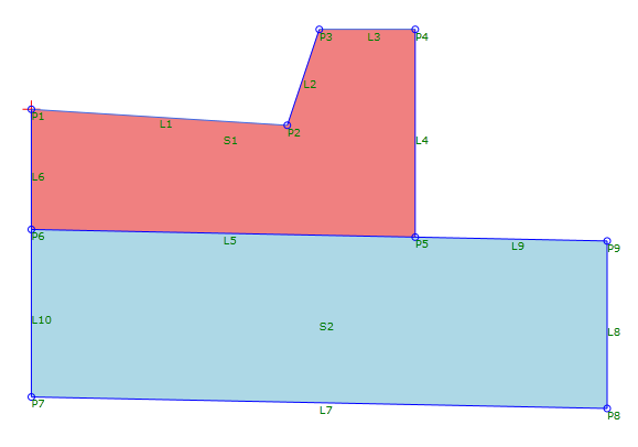
This example contains two shapes: S1 and S2.
Note: The colors of the shapes are different because each shape has a different Shape Code applied to it.