Fillet Arc
Add a fillet at the intersection of two links.
Properties
Specify the following parameters in the Properties panel.
| Link | |
| Link Number | Specifies the link number. You can change the automatically generated Link Number value. |
| Link Codes | Specifies the codes assigned to the link. |
| Geometry Properties | |
| First Link | Specifies the incoming link to fillet. |
| Second Link | Specifies the outgoing link to fillet. |
| Tessellation | Specifies the number of line segments used to represent the curve. Note: This value must be between 2 and 100.
Click [...] to open the Expression Editor, where you can enter or calculate a value. |
| Round By | Specifies the parameter by which to define the fillet:
|
| Round Parameter | The value to apply to the Round By parameter. |
| Points | |
| Start Point Name | Specifies the start point name. You can change the automatically generated value. |
| Start Point Code | Specifies the codes assigned to the start point. |
| End Point Name | Specifies the end point name. You can change the automatically generated value. |
| End Point Code | Specifies the codes assigned to the end point. |
| Miscellaneous | |
| Comment | Indicates notes about the link. Comments can be displayed in the Preview panel. |
Note: The First Link and Second Link must share a point. The start point is located on the First Link, and the end point is located on the Second Link.
Example
To see an example of how this geometry element is used, open the following Sample PKT file:
Fillet Arc Example.pkt
The example PKT contains an example of a fillet arc link. To review the parameters, select the Fillet Arc link in the Flowchart, and then see the Properties panel.
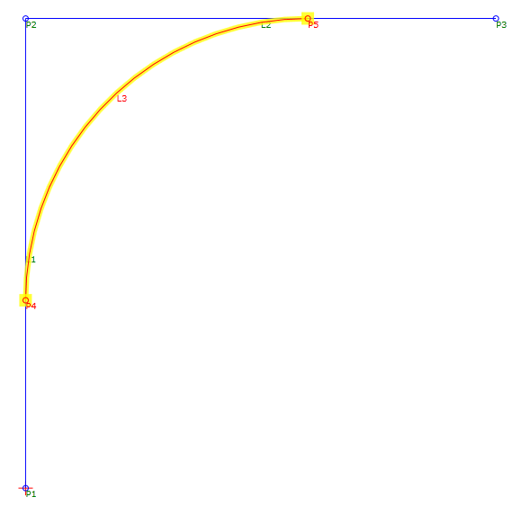
In the example, L3 forms a fillet between L1 and L2. L3 is defined by a radius value of 3, and has a Tessellation value of 20. If either of the links is modified, L3 retains its defining parameters, as well as its tangency to L1 and L2.