In this exercise, you will define the geometry of the drop inlet manhole by creating a simple schematic of the structure profile. You will build this portion with dimensions that can be modified from within Autodesk Civil 3D when the part is in use.
This exercise continues from Exercise 1: Defining the New Part in the Structure Catalog.
- Expand Modeling
 Work Planes, right-click Vertical AxisSet View. The current view and UCS is set to match the work plane.
 - Right-click Vertical Axis, and then click Add GeometryLine.
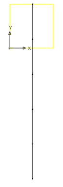
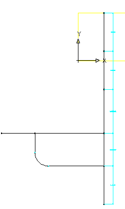
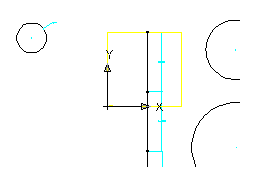
Create a line with 5 segments on the work plane. Begin by snapping to the node of the reference point on the Rim work plane and Use Ortho to make it easier to draw a straight line. Make the segments about 24 units long. A line geometry object is shown in the drawing. This line represents the vertical axis of the manhole. Each segment represents a component of the structure. Starting from the top, the segments represent the frame, the cone, and the last 3 segments represent the barrel. You will use the extra vertices to place the incoming Dip Tee and the Drop 90° Elbow in the next steps.
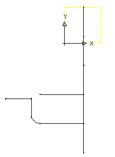
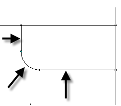
- Use the Add GeometryLine and Add GeometryArc to draw the schematic of the drop assembly. Don’t worry about making the parts perfectly meet. You will use constraints to make the geometry match up properly. Make the two horizontal lines that connect to the vertical line about 36 units long. Next you will establish some constraints to keep the components of the profile in the correct location relative to one another.
- Right-click Vertical AxisAdd ConstraintsParallel. Select the bottom line segment of the manhole centerline, and then click the segment directly above it. The bottom two segments are now constrained such that they are parallel to each other.
- Repeat the process, working your way up the centerline, constraining adjacent line segments to Parallel. All segments representing the centerline of the structure are constrained to be parallel to one another.
- Right-click Vertical AxisAdd ConstraintsPerpendicular. Select the bottom segment of the structure centerline and the lower horizontal line.
- Repeat for the upper horizontal line. The lower and upper horizontal components of the drop pipe are constrained to perpendicular to the structure centerline.
- Right-click Vertical AxisAdd ConstraintsParallel. Select the bottom line segment of the manhole centerline and then click the vertical segment of the drop pipe. The vertical drop pipe is constrained to parallel to the structure centerline.
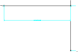
- Right-click Vertical AxisAdd ConstraintsCoincident. Click the point at the top of the vertical drop pipe, and then the left end of the upper horizontal line. This positions the rectangle so that its center is located at the fixed point.
- Right-click Vertical AxisAdd ConstraintsParallel. Select the right upper horizontal segment, and then the left upper horizontal segment. The two upper segments are constrained to parallel.
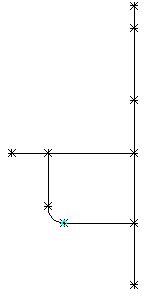
- Right-click Vertical AxisAdd ConstraintsTangent. Select the lower horizontal line, and then the arc. Repeat for the arc and the vertical segment of the drop pipe. The drop pipe bend arc is constrained to be tangent with the horizontal and vertical segments of the pipe.
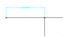
- Right-click Vertical AxisAdd DimensionDistance. Click the bottom and then top points at the ends of the top segment of the centerline. Click a point to set the location of the dimension. A dimension named LenA1 is created for the line segment representing the frame height.

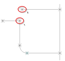
- Repeat these steps for each segment of the centerline, starting at the top and ending at the bottom segment. Dimensions named LenA2 through LenA5 are created for the centerline of the structure. Note:
For this exercise, make sure you dimension the segments in the order shown in the following illustration.
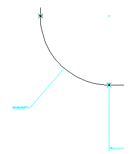
- Add a Distance dimension to the lower horizontal line by picking the points at each end. This represents the distance from the structure centerline to the start of the elbow. This is used to ensure that the drop stays on the outside of the structure. LenA6 is created.
- Right-click Vertical AxisAdd DimensionDiameter. Select the arc that represents the elbow. Click a point to set the location of the dimension. BdyD1 is added to the arc.
- Add one final length dimension to the left upper horizontal line segment. LenA7 is added.
- Click Save Part Family. The part is saved.
Next you will add Profiles that represent the diameters of the frame, top of cone, barrel, and drop pipe.
First, you’ll create the profile for the frame diameter.
- Right-click Vertical AxisAdd ProfileCircular. Click an open area near the top right of the vertical axis to define the center and then click again about 12 units away to define the diameter. A circle profile is drawn.
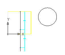
- Right-click Vertical AxisAdd DimensionDiameter. Click the circle drawn in the previous step. Click a point to set the location of the dimension. BdyD2 is created for the frame diameter.
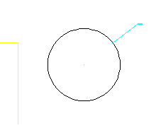
- Expand Vertical Axis. Right-click Circular ProfileRename. Enter “Frame Cylinder Diameter”. This will make it easier to work with this shape later.
- Next, repeat the previous two steps to create and dimension the top of cone profile with a radius of about 18 units, and the barrel profile with a radius of about 24 units. The top of cone profile is drawn and dimensioned with BdyD3. The barrel diameter profile is drawn and dimensioned with BdyD4.
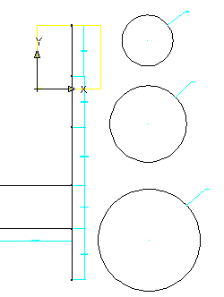
- Next, create and dimension the drop pipe profile. Right-click Vertical AxisAdd ProfileCircular. Click an open area to the left of the upper end of the vertical axis to define the center and then click again about 6 units away to define the diameter.
- Add a diameter dimension to the pipe profile. The pipe profile is created and dimensioned with BdyD5.
- Rename the three Circular Profiles to Cone Top Diameter, Barrel Cylinder Diameter, and Drop Pipe Diameter. Renaming the profiles will make them easier to work with later.
- Click Save Part Family.
The next exercise continues working on this part.
To continue this tutorial, go to Exercise 3: Creating Profiles and Establishing Parameters.