You can use the Profile Locking tab in the Profile Properties dialog box to specify how the layout profile geometry is anchored in relation to the associated alignment.
Anchor Profile Geometry Points To Alignment Geometry Points
The Anchor Profile Geometry Points To Alignment Geometry Points option locks each profile geometry point to the previous alignment geometry point. If the alignment changes, the elevation of the profile geometry point is maintained and the profile entities that are affected by the edit to the alignment are modified or deleted.
This option preserves portions of a layout profile that are not affected by a change to the horizontal geometry.
If you choose to anchor the profile geometry points to the associated alignment geometry points, then you can also specify whether notifications are displayed and whether profile geometry is modified or deleted when the geometry of the alignment is changed. If you choose to have notifications displayed, then a notification icon is displayed at each affected geometry point in the drawing. The notifications also appear in the Profile Entities vista when Entity Based mode is selected in the Profile Layout Tools toolbar.
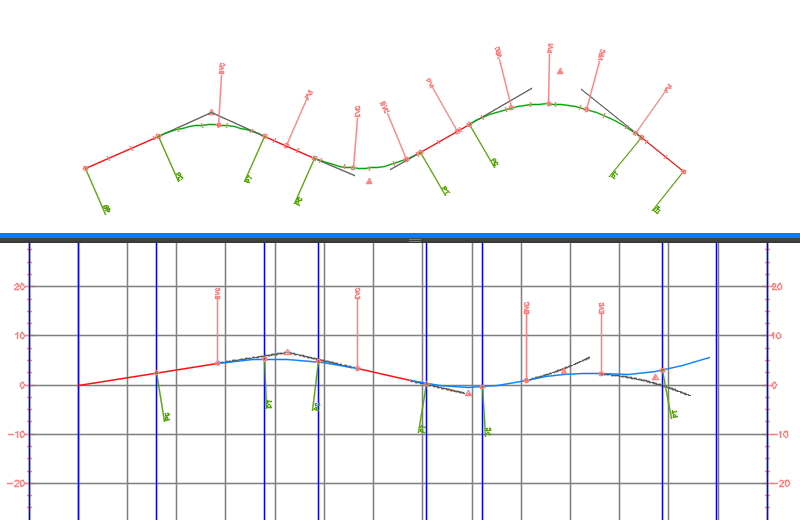
The following illustration shows an alignment (upper viewport) and its associated profile (lower viewport).

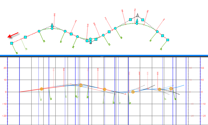
In the following example, the Anchor Profile Geometry Points To Alignment Geometry Points option is specified for the profile. When the start point of the alignment is grip-edited to the left (indicated by the red arrow in the illustration below), making the alignment longer, the profile is modified and the modified geometry is marked with notification symbols. The original drawing is inserted as an xref so that you can see how the alignment and profile are changed by the edit. The xref shows the original geometry in lighter colors.

There may be situations where a solution cannot be found for the profile geometry when the alignment is edited. In this case, when a solution cannot be found, the profile entities will be deleted, creating gaps in the profile. If the profile geometry is broken to create a gap, it is broken at the nearest vertical geometry point that is outside the affected region.
Anchor Profile To Alignment Start
Anchor Profile To Alignment Start option locks the profile to the alignment start. If the horizontal alignment changes, the profile geometry does not change, and stays locked relative to the alignment start station. This setting replicates the behavior that was in versions of the application prior to the 2015 version.
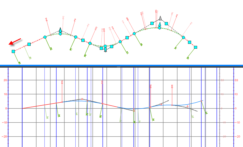
In the following example, the Anchor Profile To Alignment Start option is selected. When the start point of the alignment is grip-edited to the left (indicated by the red arrow in the illustration below), making the alignment longer, the profile stays locked to the start point of the alignment and it moves left with the alignment start point.
