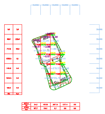
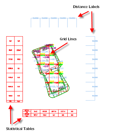
You can use the Earthwork Plan Production command to insert labels in a grid and tables that contain information about the volume of the earthwork between two TIN surfaces. The following illustration shows an example of the grid, labels, and tables that are inserted into a drawing when using this command.
-
Click
Analyze tab
 Volumes and Materials panel
Earthwork Plan Production
Find.
Volumes and Materials panel
Earthwork Plan Production
Find.
The Create Earthwork Construction Plan dialog box is displayed.
- Select the existing ground TIN surface.
- Select the finished ground TIN surface.
- Optionally, select a grid point. This point specifies how the grid lines are positioned. When the grid is created, one of the grid intersection points will be created at this location if it is inside the specified surfaces.
- Optionally, select a 2D polyline as a boundary.
Tip: To extract a polyline from a surface to use as a boundary, you can use the Extract Objects command to convert the boundary of the surface to a 3D polyline and then use the Convert 3D to 2D Polyline command to convert it to a 2D polyline.
- Specify the following
Grid Line parameters:
- Horizontal Interval: Specifies the horizontal length of the each grid cell.
- Vertical Interval: Specifies the vertical length of the each grid cell.
- Rotation Angle: Specifies the rotation angle for the grid cells.
Tip: If grids with wider intervals are not created to include the edges of the surface, set the Grid Line parameters to smaller intervals in order to create grids that include all of the surface parts. - Specify the following
Component Visibility parameters:
- Statistical Table: Displays the total cut and fill values and totals for each row and column of the grid.
- Distance Label: Displays the grid interval values.
- Grid Line: Displays the grid lines.
- Select an
Algorithm:
- Accuracy Method:
Calculates the volume from a volume surface that is created between the two TIN surfaces. This is the default method.
Note: This method should be used in cases where the grids are cut to irregular shapes at the surface boundary.
- Triangular Prism Method: Calculates the volume from triangular prisms. The area to be calculated is divided into triangular prisms, and the volume is calculated for each triangular prism and then summed.
Note: This method should not be used in cases where the Horizontal Interval and Vertical Interval are set to different values.
- Cuboid Prism Method: Calculates the volume from cuboid prisms. The area to be calculated is divided into cuboid prisms, and the volume is calculated for each cuboid prism and then summed.
- Accuracy Method:
Calculates the volume from a volume surface that is created between the two TIN surfaces. This is the default method.
- Click
 in the Settings row to open the
Display Settings dialog box.
in the Settings row to open the
Display Settings dialog box.
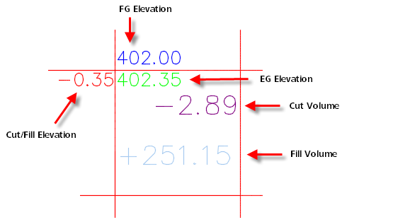
- In the
Display Settings dialog box, use the options at the top to specify layer, text, and location settings. The following illustration shows how various labels appear in the drawing:
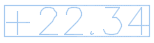
- Select the
Volume Text Boundary check box to insert a boundary around the volume label text, as shown in the following illustration:
- Under
Irregular Cell Label Options, you can specify settings that are used when the edge of the selected boundary causes a grid cell to have an irregular shape.
Note: These options are used when a boundary is selected in the main dialog box.
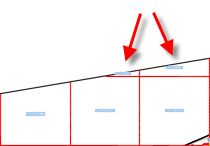
- Boundary Point: Specifies that when the shape of a grid cell is irregular, a symbol label is used, the original elevation labels are used, or no elevation labels are used.
If you select Symbol Label, symbols are inserted at the locations where cells are irregular and information about those points is inserted into a table in the drawing.

-
Boundary Volume: Specifies how the volume label is placed when the shape of a grid cell is irregular.
If you select Original Label, the label is placed at the center of the irregular grid cell area, as shown in the following illustration.
If you select Whole Grid Label, the label is placed as if the grid cell was whole, as shown in the following illustration.

- Boundary Point: Specifies that when the shape of a grid cell is irregular, a symbol label is used, the original elevation labels are used, or no elevation labels are used.
- Click OK to close the Display Settings dialog box.
- Click
OK in the
Create Earthwork Construction Plan dialog box to create the earthwork construction plan in the drawing.
Tip: You can click Delete in the Create Earthwork Construction Plan dialog box to delete all components of an existing earthwork construction plan from the drawing.