- Create a corridor model for an alignment.
- Optionally, create feature line styles with different colors and apply them to the feature lines in the corridor model. For example, create a blue Edge Of Pavement style to distinguish it from a red Shoulder style.
- Use the Feature Lines tab of the Corridor Properties dialog box to assign the feature line styles to the feature lines. This step helps distinguish the feature lines for easier selection when you are creating the corridor boundaries. A corridor boundary specifies an area of the corridor to render using a specified render material.
- Use the Surfaces tab of the Corridor Properties dialog box to create a corridor surface. For example, create a surface using the Links data type and the Top code. Assign a simple surface style that does not have triangles visible, such as border and contours only. Note: You can more easily create the corridor boundaries if the triangles are not visible.
- Select the Render Material for the corridor surface.
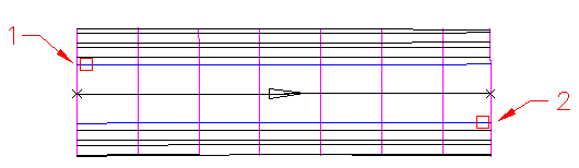
- Optionally, use the Boundaries tab of the Corridor Properties dialog box to create corridor boundaries that correspond to the areas on the corridor that you want to render with a specific material. You create the boundaries by selecting corridor feature lines that form the boundaries of the area. You should select the bottom end of one feature line followed by the top end of its pair.
For example, select the bottom outside edge of the lane followed by the top outside edge of the lane to create a boundary that encompasses both lanes:
- Use the AutoCAD Render command to render the corridor.